Structures and shadow
Footprints and heights for the control rooms, unit substations, objects, arresters and street lights on the Site tab — and the shadow they clear tables out of.
Structures & Shadow (keep-clear) describes every building and pole on the site. The numbers you enter here do two separate jobs.
First, they set the physical footprint of each structure — the rectangle it occupies on the ground. That rectangle is what is drawn on the plot, what is reserved out of the array, and what is carried into the exported drawings. Any table overlapping it is removed.
Second, the heights of the buildings and objects drive a year-round shadow footprint. The application sweeps the sun through a working window of the day, across the whole year, and takes the ground each structure's shadow covers at any point in that sweep. Tables inside that footprint are cleared rather than placed, so no part of the array sits permanently in a building's shadow.
The card is the third one on the Site tab, under Site Parameters. Its top half is a grid of compact fields with the column headers L, W and H; the rows below it come in pairs.
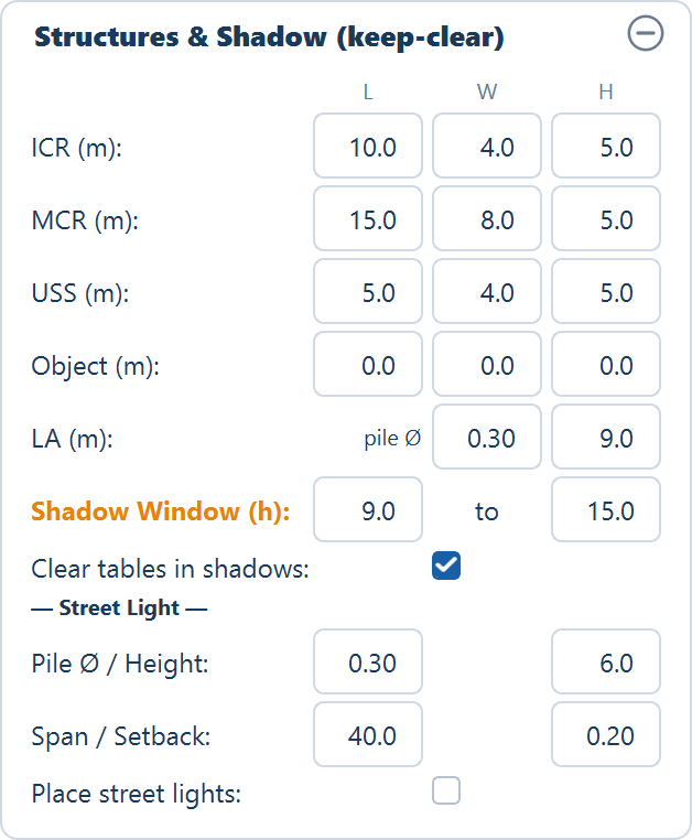
Nothing on this card is kept in a project file. Footprints, arrester fields, the shadow window, the clear-in-shadows tick and the street-light settings all come back at the values below when a saved project is opened, whatever you had set when you saved it. Record any non-default values in your own design notes.
The four structures
Every footprint is entered as L — length, east–west — by W — width, north–south — with H, the height, beside it. The fields carry no unit; the row labels do (ICR (m):), and every value is in metres. The layout uses the values in these fields, not any fixed size, so a room you size differently here is placed and drawn at the size you asked for.
| Row | L (m) | W (m) | H (m) |
|---|---|---|---|
| ICR (m): | 10.0 | 4.0 | 5.0 |
| MCR (m): | 15.0 | 8.0 | 5.0 |
| USS (m): | 5.0 | 4.0 | 5.0 |
| Object (m): | 0.0 | 0.0 | 0.0 |
The ranges are the same for all four rows: length 0.0–500.0 m, width 0.0–500.0 m, height 0.0–200.0 m, to one decimal place.
ICR — inverter control room
The building that houses the inverter and switchgear equipment for one block of the array. One is placed automatically for each block of DC capacity, and the block size is set by ICR Block in Site parameters.
Control rooms are the structures that most often cost you tables, because there are several of them and each sits in the middle of the array it serves rather than off to one side. Every table overlapping a room's footprint is removed, and the plant capacity is recomputed afterwards.
MCR — main control room
The plant's central control building, and the point every medium-voltage circuit terminates at. Unlike the inverter control rooms it is not placed automatically — you place it yourself, once, from the Main Control Room & Objects card on the Tools tab: arm Place MCR and click a position on the plot. A position outside the boundary is refused with Please place inside the boundary. The Tools tab is unlocked once a layout exists.
Its footprint is the largest of the three buildings by default, so place it where the array is already interrupted — beside the entrance, next to the switchyard, or on ground the terrain or an obstruction has already excluded — rather than in the middle of a well-packed block.
Where you put it also sets the plant's medium-voltage cable length. Every inverter control room's circuit runs back to this building, and the circuits are routed as one shared network rather than as parallel runs, so nearby rooms merge into a single trench. A position central to the control rooms costs materially less cable than a corner does. The medium-voltage cables are routed on the next Generate Layout with cable calculation on — after placing the room the card says so — and the total then appears on the status line and in the Summary view. See Cable routing.
USS — unit substation
A local step-up substation for a plot that does not contain the main control room. See Unit substations in a multi-plot file below for when one appears.
Object
A generic structure you place by hand — a store, a pump house, a security post, a switchyard building, anything on the site the boundary file did not carry. On the Tools tab, arm Place Object, click the plot, and repeat for as many as you need; Remove Objects clears them. Place Object becomes available as soon as the object has a size.
All three of its fields ship at 0, which means not configured. Set the length, width and height before placing objects, or you are placing a structure with no footprint and no shadow.
Once sized, an object behaves like a building in every respect that matters here: its footprint is reserved out of the array, tables overlapping it are removed, and its height casts the same year-round shadow a control room does. The card carries one set of object dimensions, so every object you place takes that same size. On a site with a large store and a small security post, size for the structure whose shadow you care about and draw the rest as annotations.
The heights of these four structures are used for shadow geometry. They are not a structural design, and nothing here is checked against a load case.
Unit substations in a multi-plot file
On a site made up of several separate boundaries, the medium-voltage collection cannot all run to one building without crossing ground you do not own. The application handles this the moment you place the main control room:
Place the main control room in one plot
Arm Place MCR and click inside each plot in turn. The last unassigned plot you click receives the main control room.
A unit substation appears in every other plot
A unit substation of the size set above is dropped into every plot except the one holding the main control room — one per plot.
Each plot collects to its own substation
The inverter control rooms in a plot route their medium-voltage cables to that plot's unit substation, not across the gap to the main control room. Each plot becomes a self-contained collection network.
The remaining link — from each unit substation onward to the main control room — is an overhead line or a buried cable on a route only you can decide, across land the file does not describe. It is handled outside the automatic medium-voltage routing, so it is neither drawn nor included in the reported medium-voltage cable length. Add it to your own single-line diagram and your own schedule of quantities.
Multi-plot sites covers how several boundaries are laid out and summarised together.
Arrester pile and height
One paired row, LA (m):, holds two fields for the lightning arrester masts themselves. They sit here because the mast is a structure; whether arresters are placed at all, and how far apart, is set on the Site Parameters card above.
| Field | Default | Range | What it does |
|---|---|---|---|
| LA (m): pile Ø | 0.30 m | 0.0–5.0 m | Nothing. A design figure you record, and no more. |
| LA (m): height | 9.0 m | 0.0–100.0 m | Nothing. A design figure you record, and no more. |
Neither of these two fields changes any output. The mast height casts no shadow and clears no tables; the pile diameter reaches no quantity, no pile schedule and no export. Neither value is kept when the project is saved. The arrester mast and its foundation belong in your own structural and civil documents.
The tables cleared around an arrester come from the arrester's own keep-clear footprint, which is a fixed rectangle for the mounting type rather than anything derived from the height — see Lightning arresters.
The shadow window
| Field | Default | Range | What it does |
|---|---|---|---|
| Shadow Window (h): | 9.0 to 15.0 | 4–12 / 12–20 solar hours | The part of the day the year-round shadow footprint is swept over. |
| Clear tables in shadows: | on | — | Removes tables and tracker units that fall inside that footprint. |
The window is set in solar hours, so 12.0 is solar noon at the site rather than noon on a clock. The first field is the start of the window and the second is the end, and their ranges are arranged so the window always spans solar noon.
The default window runs from 9.0 to 15.0 — the six hours around solar noon. As the field's own tooltip puts it, this is the usual shadow-free design window, and the winter solstice governs it. A later end adds the low-sun afternoon tail and roughly doubles the ground each 5 m building sterilises. Narrowing the window shrinks the footprint, because the early-morning and late-afternoon shadows, which are the long ones, are left out of the sweep.
Two things make the resulting footprint larger than the shadow you would see at any single moment:
- It is swept across the day, so it fans from the western side of the structure round to the eastern side.
- It is swept across the year, so it takes the winter shadow length, not the summer one.
In the northern hemisphere the swept area therefore lies on the northern side of the structure; in the southern hemisphere, the southern side. Placing the main control room on the equator-facing edge of a block costs fewer tables than placing it on the pole-facing edge.
Clear tables in shadows
On by default. It removes every table or tracker unit falling inside the year-round shadow footprint of the inverter control rooms, the main control room and any objects you placed. The status line after a run counts them: n tables cleared for building shadows.
That list is exactly three structures. Arrester masts are not in it — no arrester shadow clears a table, at any height you enter — and street-light shadows are handled by the street-light option rather than by this one.
The reasoning is straightforward. A module that spends the productive part of every day in a building's shadow does not earn its place: it produces a fraction of what its neighbours produce, it drags the string it belongs to down with it through mismatch, and it still costs a full set of modules, piles and cable. It is better removed than placed. The plant's capacity, module count and bill of materials all report the smaller, honest number.
Turning it off places tables everywhere they geometrically fit, shadow or not. That is useful when you want to see the maximum capacity a site can carry, or when you have not yet decided where the buildings go. It is not the configuration to issue a design from.
Row-to-row shading between the tables themselves is a different matter — it is never a reason to remove a table, and it is handled as a loss in the energy model. See Shading losses.
Street lights
The bottom of the card, under a Street Light divider, holds two paired rows and a tick.
| Field | Default | Range | What it does |
|---|---|---|---|
| Pile Ø / Height: pile Ø | 0.30 m | 0.0–5.0 m | The diameter of each pole's foundation. |
| Pile Ø / Height: height | 6.0 m | 0.0–50.0 m | The pole height above ground, and the height its shadow is cast from. |
| Span / Setback: span | 40.0 m | 1.0–500.0 m | The pole-to-pole spacing along the perimeter. |
| Span / Setback: setback | 0.20 m | 0.0–50.0 m | How far inside the perimeter the poles are inset. |
| Place street lights: | off | — | Whether poles are placed at all. |
With the option on, poles are placed along the perimeter, spaced by the span, just inside the fence, and any table their shadow touches is cleared.
The count follows from the span: it is approximately the plant perimeter divided by the pole-to-pole span. Raising the span thins the poles out and lowers the count; lowering it does the reverse. The figure appears on the Street lights row of the Summary view.
The setback is small — a fraction of a metre by default — so with a perimeter road of any usual width the poles land inside the road band rather than in the array, and the ground they stand on was already kept clear. What can still cost you tables is the shadow, which reaches inward from the fence line toward the first row of the array.
Site equipment covers the placed poles, the main control room and the objects on the plot.