Main control room, substations and street lights
Placing the main control room and other structures from the Tools tab on a generated layout, and the perimeter street lights you enable before generating.
Some site equipment is not placed with the layout. The MCR — main control room — and any generic objects are placed by clicking a position on the plot, from the Main Control Room & Objects card of the Tools tab. Unit substations appear on their own when a multi-plot site gets its main control room. Street lights are a setting on the Site tab that you turn on before you generate.
The inverter control rooms — ICRs — are different: they are counted from the plant capacity and sited automatically. See Inverter control rooms.
| Equipment | How it arrives | When | Footprint set in |
|---|---|---|---|
| MCR — main control room | You click Place MCR, then click the plot | After a layout exists | Structures & Shadow, the MCR row |
| Object — anything else on the site | You click Place Object, then click the plot | As soon as the object has a size — a layout is not needed | Structures & Shadow, the Object row |
| USS — unit substation | Placed for you, one per plot, when the main control room is placed | Multi-plot sites only | Structures & Shadow, the USS row |
| Street lights | Placed with the layout | Enabled before generating | Structures & Shadow, the street light rows |
The placement card
The Tools tab is locked until a layout exists — its tooltip reads "Generate a layout first" and its buttons are greyed out. Once a layout is on screen, the Main Control Room & Objects card offers Place MCR, Remove MCR, Place Object and Remove Objects, with a hint line under them that tells you what the next click on the plot will do.
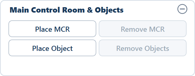
Placing the main control room
Click Place MCR
The button changes to Cancel Placement while it is armed, and the hint reads "Click on the plot to place the MCR.", so you can always tell whether the next click on the plot will drop a building. Click Cancel Placement to disarm it without placing anything.
Click the position on the plot
The main control room is placed at the point you click. One click places it and the button returns to Place MCR.
Keep it inside the boundary
A click outside the plant boundary is refused with the message "Please place inside the boundary." Nothing is placed, and the button stays armed so you can click again in the right place.
Generate again to route the medium-voltage cables
As soon as the room is dropped the hint reads "MCR placed. Enable 'Cable Calc' and regenerate layout to route MV cables." Placing the room gives the medium-voltage network its destination; it does not route anything. Tick Calculate cables on the Cables card of the Electrical tab if it is not already on, and click Generate Layout.
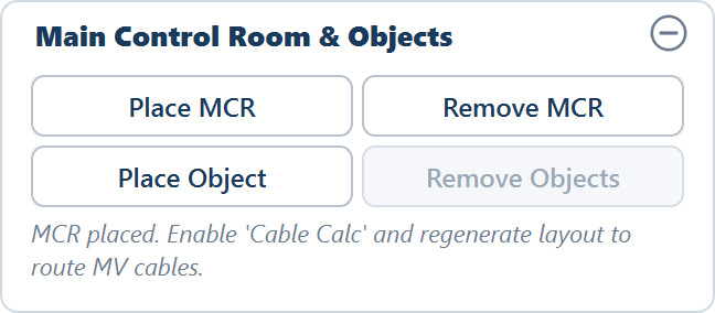
After that run the status line adds "| MV cable: n m", the MV cables (ICR→MCR) row of the Layers popover has something to draw, and the MV cable (m) row of the Summary view is filled in. Remove MCR is enabled while a room exists.
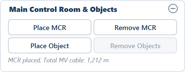
Remove MCR takes the room away again. Place it once more wherever you want it, then generate again to re-route the medium-voltage cables to the new position.
The footprint
The main control room's size comes from your own fields on the Structures & Shadow (keep-clear) card of the Site tab, not from a fixed value:
| Field | Default | Unit |
|---|---|---|
| MCR length (east–west) | 15.0 | m |
| MCR width (north–south) | 8.0 | m |
| MCR height | 5.0 | m |
Length is always the east–west dimension and width the north–south one, so a building entered as 15 by 8 is wide across the rows, not along them. The height drives the shadow footprint rather than the plan area. Set these before you place the building; see Structures and shadow for the whole card, including the Clear tables in shadows option, which is on by default and removes tables that fall inside the building's year-round shadow.
Why the main control room comes first
Medium-voltage routing runs from every inverter control room to the main control room. Until the main control room exists there is no destination, so no medium-voltage cable is routed at all — the MV cable (m) and MV trench (m) rows of the Summary view read a dash even on a run with cable calculation switched on.
Medium-voltage cables are routed on the next Generate, not when the room is
placed. Until you generate again with Calculate cables on, the MV row of the
Layers popover has nothing to show and the Summary's MV cable (m) reads
—, however long ago you dropped the room.
The order that works is therefore:
- Generate the layout.
- Place the main control room.
- With Calculate cables ticked, generate again.
- Read the medium-voltage figures.
Place it where the plant's export actually leaves the site — usually near the point of interconnection — because the trunk network is built to reach it and its position sets the whole medium-voltage cable length. Moving it changes that length. See Cable routing and trenches for how the trunk is formed and what the reported lengths mean.
Placing generic objects
An object is anything on the site that keeps modules off the ground around it and that your boundary file does not carry: a tree, a pole, a tank, an existing shed, a structure the survey missed.
- Place Object arms placement in the same way as Place MCR — the button reads Cancel Placement while armed, and a click outside the boundary is refused with the same message.
- Place Object is the one button on the card that does not wait for a layout: it is enabled as soon as the Object row has a length, a width and a height, so you can mark a tree or a tank before the first run and let the layout be built around it.
- Remove Objects clears the objects you have placed.
Their size and height come from the Object row of the Structures & Shadow card:
| Field | Default | Unit |
|---|---|---|
| Object length (east–west) | 0.0 | m |
| Object width (north–south) | 0.0 | m |
| Object height | 0.0 | m |
All three object fields ship at 0.0, which means not configured. Fill in a length, a width and a height before you place an object, or you are placing something with no extent and no shadow.
The point of an object is the shadow, not the footprint. With Clear tables in shadows on, the year-round shadow of each object across the shadow window clears the tables it falls on — which is exactly what you want for a tree that no boundary file will ever describe. The height is what makes that shadow long, so it is the field to get right.
Unit substations on a multi-plot site
A USS — unit substation — is placed for you, and only on a site whose boundary file contains more than one plant boundary.
On a multi-plot site the hint under Place MCR changes to "n plots — click INSIDE each plot to drop a USS (Unit Substation). The LAST unassigned plot you click gets the MCR. Each plot's ICRs route to its own USS/MCR." Click inside each plot in turn: every plot you click receives a unit substation, and the last plot you click receives the main control room instead. Each plot's inverter control rooms then route their medium-voltage cables to the building in their own plot instead of running across country to the main control room.
| Field | Default | Unit |
|---|---|---|
| USS length (east–west) | 5.0 | m |
| USS width (north–south) | 4.0 | m |
| USS height | 5.0 | m |
The link from a unit substation onward to the main control room is an overhead line or a buried cable, and it is not part of the automatic medium-voltage routing — plan and cost it outside the application. See Multi-plot sites for the full behaviour, including how each plot gets its own column in the Summary view.
Street lights
Street lights are perimeter lighting: a line of poles set close inside the fence, right around the plant.
They are off by default and, unlike the main control room, they are not placed by clicking. Tick Place street lights on the Structures & Shadow card of the Site tab before you click Generate Layout; a layout already on screen does not gain them.
What placement does
- Poles are spaced along the plant perimeter at the pole-to-pole span.
- Each pole sits inside the fence, inset by the street light setback.
- Any module table the pole's shadow touches is cleared, so lighting costs a little capacity around the edge of the plant.
The number of poles is approximately the perimeter divided by the span, so a long, irregular boundary carries more lights than a compact one of the same area.
The street light settings
All of them are under the — Street Light — divider of the Structures & Shadow card:
| Field | Default | Range | Unit |
|---|---|---|---|
| Pile Ø | 0.30 | 0.0–5.0 | m |
| Height | 6.0 | 0.0–50.0 | m |
| Span | 40.0 | 1.0–500.0 | m |
| Setback | 0.20 | 0.0–50.0 | m |
| Place street lights | off | — | — |
What each one changes:
- Span sets the pole count. Widen it for fewer poles and less cleared ground; narrow it for more of both.
- Setback decides how far inside the fence the poles stand. It is small by default, which keeps the poles in the perimeter road band rather than out among the tables.
- Height sets how far the pole's shadow reaches, and therefore how many tables it clears.
- Pile Ø describes the foundation.
None of these settings is kept in a project file; a reopened project shows the defaults.
Reading the result
The Summary view reports the pole count in the Street lights row, one column per plant with a Total column on a multi-plot site. The module and capacity rows already account for the tables the lights cleared.
If a placement does not do what you expect
Where the structures end up in the outputs
- On the plot. The main control room, the unit substations, objects and street light poles are drawn with the rest of the layout; the main control room is violet.
- In the CAD drawing. The main control room is written to its own
MCRlayer, objects toOBJECTSand street light poles toSTREET_LIGHT, each with its keep-clear shadow on a layer of its own. See CAD export. Street lights are not written to the Google Earth file. - In the bill of materials. The automated list is computed from the layout, so use ⚙ Rebuild from Layout after placing or removing equipment. See Bill of materials.
Where to go next
Cable routing and trenches
What medium-voltage routing does once the main control room exists
Multi-plot sites
Several boundaries in one file, one control room, a substation per plot
Structures and shadow
Every footprint, height and the shadow window that clears tables
Lightning arresters
The coverage grid, the footprint, and what it costs in capacity
Lightning arresters
How arresters are placed on a coverage grid, what each one clears from the layout, the settings that control the radius and the footprint, and where they show up.
Obstructions
Every kind of ground kept clear of modules — water, buildings, line corridors, terrain, shadows — and how to draw an exclusion by hand from the Tools tab or in Sketch Mode.