Choosing a design mode
The New design window — fixed tilt or tracker, string or central inverter — what each choice means, what it changes in the interface, and how to open a second design.
Every launch begins with two questions: how the modules are mounted, and how the plant is wired. They are asked in the SolarLayout · New design window before the main window opens, and Continue must be clicked to get any further — closing the window instead quits the launch.
The choice belongs to the window. It decides which input cards exist, how units are placed on the ground, what equipment is counted, and what the Summary view's rows are called. It cannot be changed inside the window — to work in a different design you open a second window, which the last section covers.
The New design window
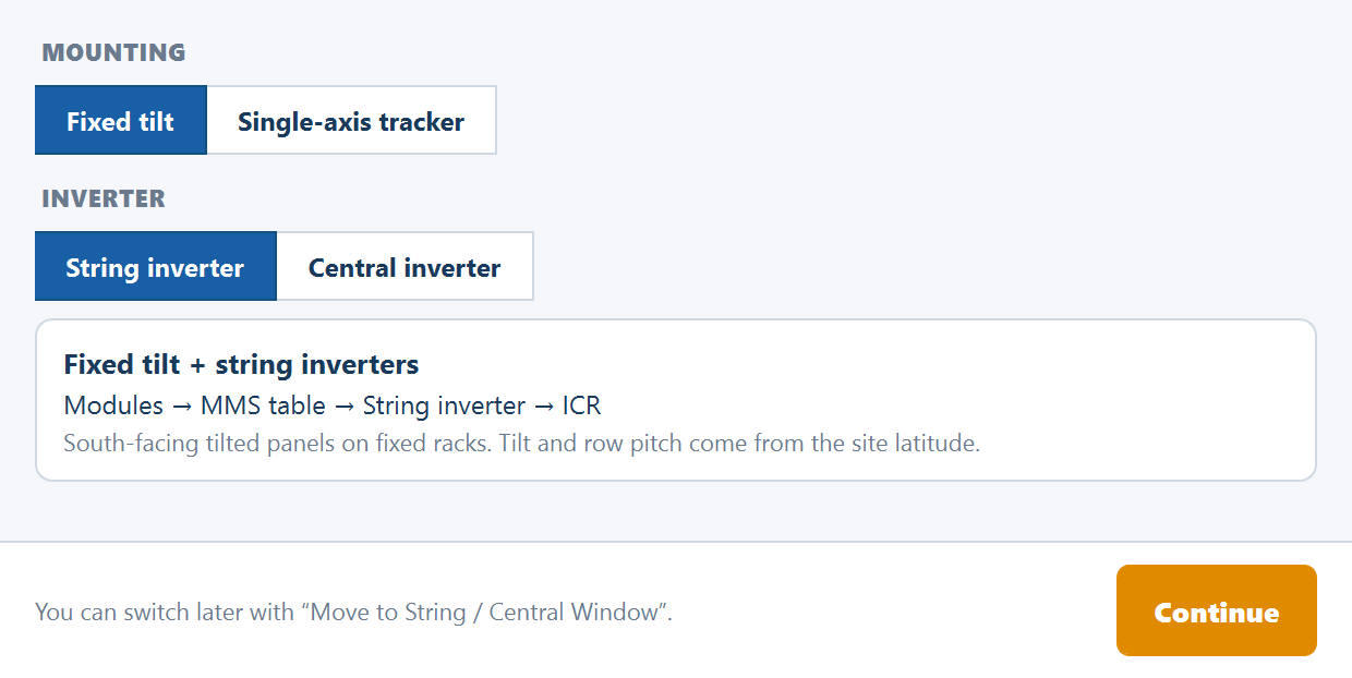
Two segmented controls, each with the left option selected by default:
| Control | Options |
|---|---|
| MOUNTING | Fixed tilt · Single-axis tracker |
| INVERTER | String inverter · Central inverter |
A summary card under them updates as you click. Its title names the combination, a chain line shows the equipment path from module to control room, and a note describes the mounting:
| Mounting | Inverter | Card title | Chain |
|---|---|---|---|
| Fixed tilt | String inverter | Fixed tilt + string inverters | Modules → MMS table → String inverter → ICR |
| Fixed tilt | Central inverter | Fixed tilt + central inverter | Modules → MMS table → SMB → Central inverter |
| Single-axis tracker | String inverter | Single-axis tracker + string inverters | Modules → Tracker → String inverter → ICR |
| Single-axis tracker | Central inverter | Single-axis tracker + central inverter | Modules → Tracker → SMB → Central inverter |
The fixed-tilt note reads "South-facing tilted panels on fixed racks. Tilt and row pitch come from the site latitude."; the tracker note reads "Horizontal N–S axis, panels sweep east to west. You set the E–W pitch." MMS is the module mounting structure; SMB is the string monitoring box; ICR is the inverter control room building.
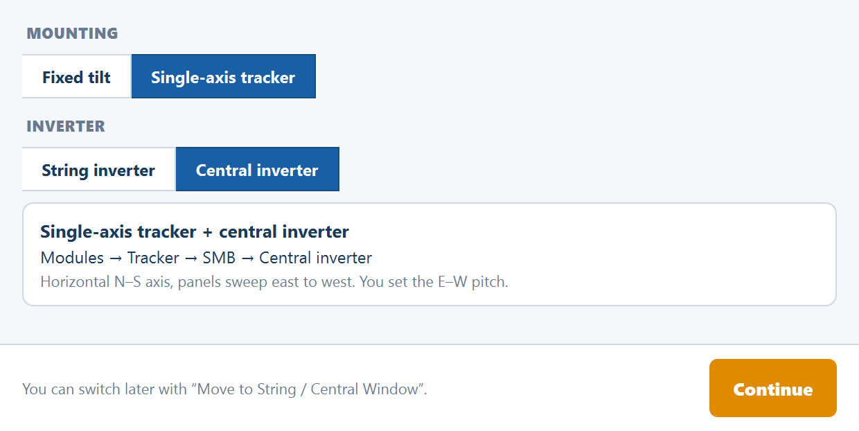
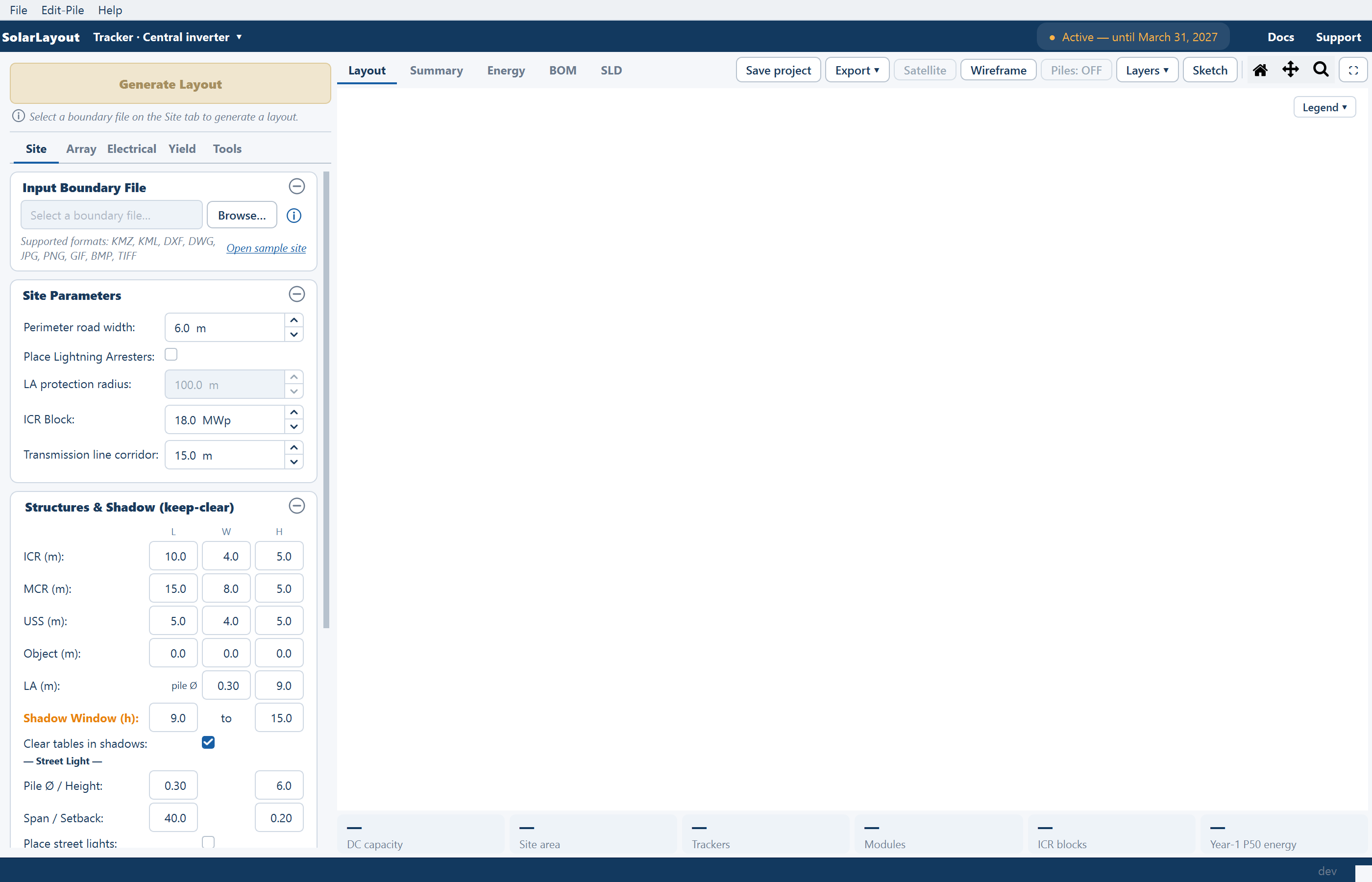
The footer reminds you that you can switch later with Move to String / Central Window. Continue opens the main window for the combination; the window title names it, and the ribbon's design chip reads it back — Fixed tilt · String inverter ▾, Tracker · Central inverter ▾ and so on.
Fixed tilt or single-axis tracker
This is a decision about the structure, and it is the one that changes the plant's geometry.
Fixed tilt. Modules sit at one angle on static racks, facing the equator — south in the northern hemisphere, north in the southern. Rows run east to west and repeat northward at a row pitch. The tilt and the pitch are derived from the site latitude unless you override them, and the pitch is what keeps one row from shading the row behind it in midwinter.
Single-axis tracker. Modules are carried on a horizontal, north–south axis and rotate about it through the day, so the panels sweep from facing east in the morning to facing west in the afternoon. There is no fixed tilt to set: what you set instead is the rotation limit the structure allows. Tracker units are long in the north–south direction and repeat eastward at an east–west pitch.
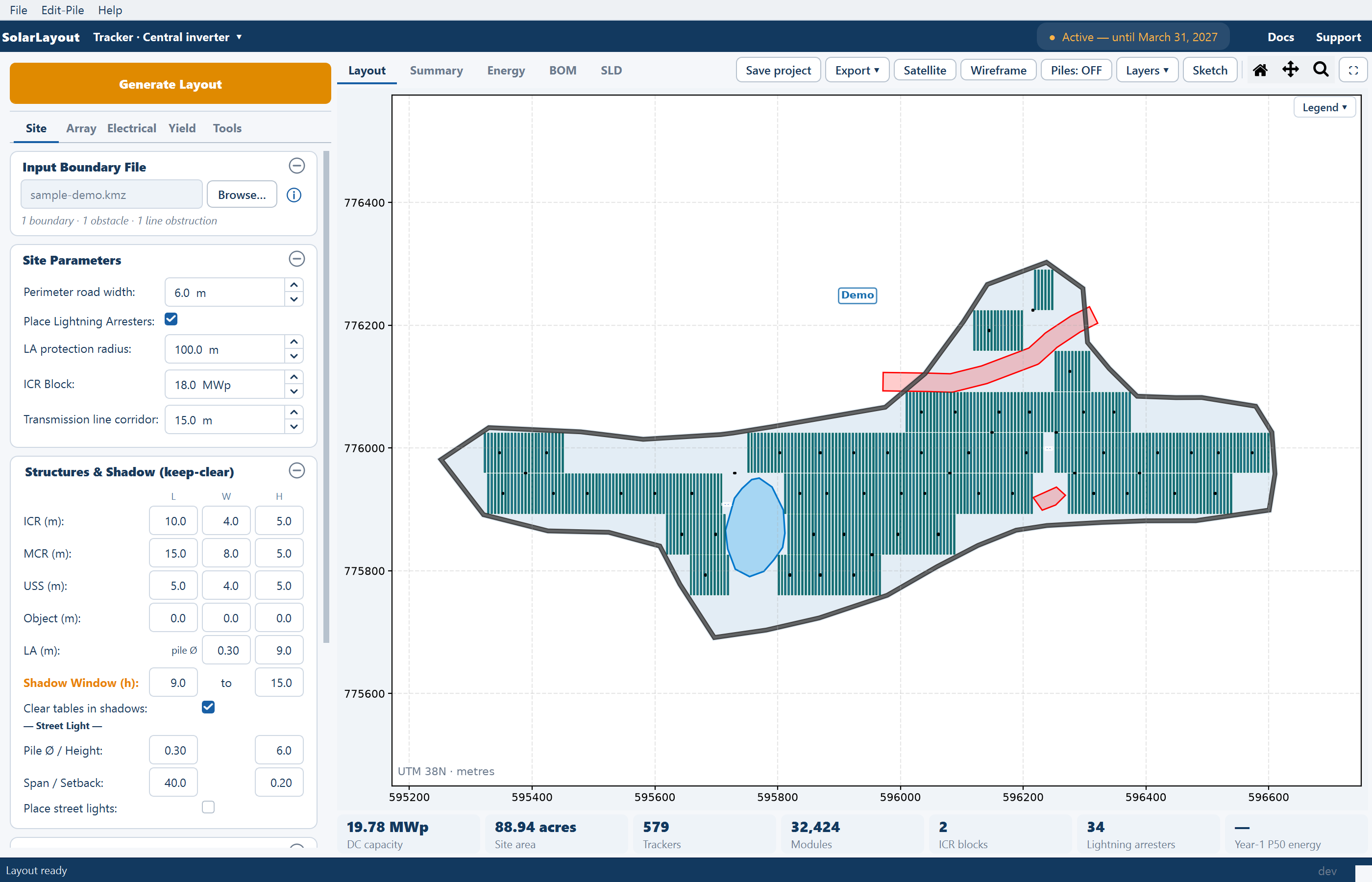
The two mountings are configured through different cards on the Array tab, under a read-only MOUNTING chip that names the one you chose:
Two cards: MMS-Table Configuration and Spacing & Tilt.
| Field | Default | Unit |
|---|---|---|
| Orientation | Portrait | — |
| Modules per row | 28 | — |
| Rows per MMS-Table | 2 | — |
| Gap between modules E-W | 0.020 | m |
| Gap between modules N-S | 0.020 | m |
| Gap between MMS-Tables | 1.0 | m |
| Override tilt angle | off — derived from latitude | — |
| Override row pitch | off — derived | — |
With portrait orientation the module's short side runs east–west and its long side north–south; landscape reverses that. A Size… button beside Modules per row opens the string-sizing calculator. See Table configuration and Spacing and tilt.
String inverter or central inverter
This is a decision about the electrical topology, and it changes what is counted and how cables are run rather than where units sit on the ground.
Many string inverters are distributed across the plant, sited in the gap bands between rows, from clusters of the tables they serve. Each is drawn as a small marker on the plot.
Cabling has two legs:
- DC string cables, table to inverter, counted twice over for the positive and negative conductors.
- AC cables, inverter to the nearest control room, counted once as a three-phase run and routed on right angles only — horizontal and vertical segments, never diagonals.
Max strings per inverter governs how many strings one inverter accepts, which in turn sets how many inverters the plant needs. One string is one row of modules within an MMS-table.
Both topologies then carry medium-voltage cables from each control room to the main control room, over a shared trunk rather than parallel runs. See Cable routing.
What changes in the interface
The design does not hide optional extras. It decides which input cards are built at all, how several labels and Summary rows read, and how a few pieces of equipment are placed.
Mounting
| In the interface | Fixed tilt | Single-axis tracker |
|---|---|---|
| MOUNTING chip on the Array tab | Fixed-tilt MMS tables | Single-axis tracker |
| Array cards | MMS-Table Configuration and Spacing & Tilt | Both replaced by a single Tracker Configuration card |
| Unit rows in the Summary view | Full tables and Half tables | Full trackers and Half trackers |
| Angle row | Tilt (°), with a trailing * when auto-calculated | Max tracking angle (°) |
| Plant chip | Tables | Trackers |
| Lightning arrester footprint | A 30 m by 7 m rectangle; tables overlapping it are removed | A 1 m by 1 m pole marker, snapped into the nearest gap between tracker columns, so no tracker units are removed |
| Cleaning robot lines | Run west to east along each table row | Run north to south along each tracker column |
| Sketch palette units | Table and Half Table | Tracker and Half Tracker |
Electrical
| In the interface | String inverter | Central inverter |
|---|---|---|
| Electrical card title | String Inverter | SMB – String Monitoring Box |
| Strings field | Max strings per inverter | Max strings per SMB |
| Extra field | — | Max SMB per Central Inverter |
| Equipment rows in the Summary view | String inverters · Inverter rating (kWp) | SMBs · SMB rating (kWp) · Central inverters · Central inverter rating (kWp) |
| Cable row | AC cable to ICR (m) | DC cable to central inverter (m) |
| Second cable row in the Layers popover | AC cables (Inv→ICR) | DC cables (SMB→CI) |
| Loss rows | String DC cable losses, AC cable losses (Str. Inv. → ICR) | The same rows read MMS → SMB and DC cable losses (SMB → Central Inv.) |
| Efficiency row | String Inverter efficiency | Central Inverter efficiency |
| CAD export layer | INVERTERS | SMB |
| Auto-built diagram | PV → String Inverter → ACCB → Transformer → MV Panel → Grid | PV → SMB → Central Inverter → Transformer → MV Panel → Grid |
| Default overload limit when sizing from an AC capacity | 1.5 | 1.4 |
The full row list, in order, is in Summary rows.
Moving to a different design
The design belongs to the window. Two controls open the New design window again — the design chip in the ribbon, and File ▸ Move to String / Central Window… (Ctrl+N). Two things about them the menu item's name understates:
- They switch the mounting as well. What opens is the same window you chose from at launch, both controls included, so the new design can be fixed tilt where the one you came from was a tracker plant.
- They open a new, independent window. The window you came from stays open beside it — the chip's own tooltip says so. This is not a mode switch applied to the work in progress, which is why two designs can be held on screen at once and read against each other.
The new window does not inherit the work in progress. Its boundary file and its inputs are entered again there, and the layout, hand edits, diagram and materials list of the window you came from stay with that window. Save each one with Save project to its own project file.
File ▸ New Project (Ctrl+Shift+N) is different: it opens a fresh window at the defaults in the same design. To compare two topologies on the same site, open the second design from the chip, load the same boundary file in each window, leave the shared inputs identical, and compare the two Summary views side by side.
Where to go next
Your first layout
A complete run in fixed tilt with string inverters
Tracker configuration
Every tracker field, its default and what it drives
Inverters and monitoring boxes
Strings per unit and the inverter file
Saving and reopening projects
What a project file keeps, and why a design change means a second window
Your first layout
A complete first run — load a boundary, generate the layout, read the plant chips and the Summary view, calculate energy, and export the report.
The main window
The ribbon, the pinned Generate Layout button, the five stage tabs of inputs on the left, the views on the right, and the status bar.