Obstructions
Every kind of ground kept clear of modules — water, buildings, line corridors, terrain, shadows — and how to draw an exclusion by hand from the Tools tab or in Sketch Mode.
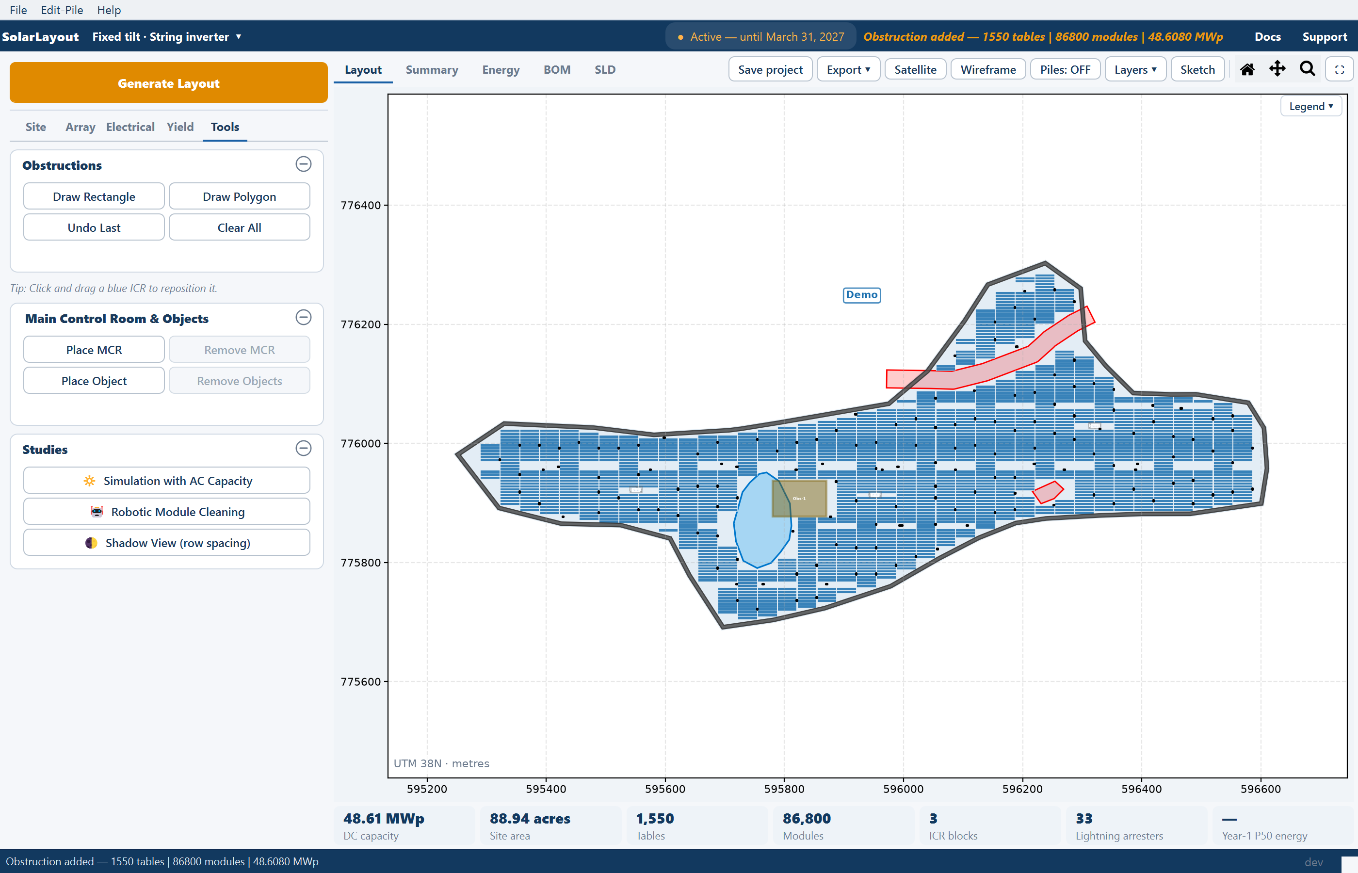
An obstruction is area subtracted from the usable area. Whatever the reason for it — a pond, a building, a transmission line corridor, steep ground, a building's shadow, or a rectangle you drew yourself — the effect on the layout is identical: the ground stops being available, and any module table overlapping it is removed.
That single rule is worth stating plainly because it makes the plot readable. Wherever you see a gap in the table grid, something was subtracted from the usable area there. This page collects every source of those gaps in one place.
How the usable area is built
The order matters, because each step works on the result of the last.
- The plant boundary is shrunk inward by the perimeter road width. What is left is the usable area.
- Polygon obstructions and water bodies are subtracted from it.
- Line features — transmission lines, canals, roads — are buffered into corridors, and those corridors are subtracted too. A transmission line or a canal takes the setback on each side; a road takes half its own width on each side.
- Terrain exclusions are subtracted, when topography is enabled.
- Tables and tracker units are then placed only where they fit entirely inside what remains.
Because a table must fit entirely inside the usable area, an obstruction clears slightly more ground than its own outline: a table that merely clips the edge of a pond is dropped in full. See How placement works.
Obstructions that come from the boundary file
A Google Earth file carries its exclusions with it, so a well-prepared file needs no hand drawing at all. Three kinds are read automatically:
| Kind | Drawn in the file as | What the application does |
|---|---|---|
| Water body | A closed polygon inside the plant boundary, named with a water keyword | Subtracted from the usable area, drawn blue, and exported as water |
| Generic obstruction | A closed polygon inside the plant boundary, any other name | Subtracted from the usable area, drawn red, and exported as an exclusion |
| Line corridor | A line — not a polygon — for a transmission line, canal or road | Buffered into a corridor and subtracted: the setback on each side, or half the road width each side for a road |
Every feature must lie inside a plant boundary. A polygon drawn outside the boundary is subtracted from nothing, so tables are placed straight over the ground you meant to keep clear. See Boundary file requirements for how each feature must be named and drawn.
Classification is by name
The application decides what a polygon is from its name, matching keywords case-insensitively — words for ponds, lakes, reservoirs and wetlands for water; words for canals, drains, nalas and rivers for a channel; words for transmission and power lines and their voltages for an overhead line.
The consequence to know:
A water body whose name carries no water keyword is treated as a generic obstruction. It still clears the tables over it, so the layout is not wrong — but it is drawn in the obstruction colour instead of blue, and it is exported on the obstruction layer instead of the water layer. Name your ponds.
That is the whole cost of a misnamed pond: presentation and the export, not placement. It is still worth fixing, because the drawing goes to a contractor who will read a red polygon as a building and a blue one as water.
Line corridors and their setback
A line feature has no width, so it cannot exclude anything on its own. A transmission line or canal is buffered on both sides by the setback, which means the corridor kept clear of modules is twice the setback you enter. A line named as a road is the exception: it is buffered by half its own width each side, so the strip kept clear is the road width, read from the boundary file rather than from this field.
| Field | Default | Range | What it does |
|---|---|---|---|
| Transmission line corridor | 15.0 per side, 30 m total | 0.0–500.0 | The distance kept clear each side of every line feature that is not a road |
The setback that suits a distribution line will not suit an export line. The application's own guidance is to raise it for higher voltages — for example 30 m per side on a 400 kV line. Set it on the Site Parameters card of the Site tab; see Site parameters.
The corridor is subtracted from the usable area exactly like a polygon, so the tables stop short of it on both sides and you get the clean service strip a line crossing actually needs.
Steep and unsuitable ground
Terrain exclusion is the same subtraction driven by elevation instead of by a drawn shape: ground steeper than your north–south and east–west slope limits, ground whose relief within a single table footprint exceeds the allowed variation, and — when you ask for it — depressions where water would pool.
It is off by default, and turning it on needs either a contour file or an internet connection for the satellite elevation model. The excluded area is reported in acres. See Topography.
Shadows of structures
The year-round shadow of a building or an object is also treated as ground to keep clear. With Clear tables in shadows on — which is the default — any table falling inside the shadow footprint of an inverter control room, the main control room or a placed object across the shadow window is removed.
This is how you exclude a tree, a mast or an existing shed: place an object with a realistic height and let its shadow clear the modules. See Structures and shadow and Main control room, substations and street lights.
Lightning arresters clear tables under their own footprint on a fixed-tilt plant — a different mechanism, described in Lightning arresters.
Drawing an obstruction by hand
Use this when the boundary file did not carry an exclusion, when a site visit found something the survey missed, or when you want to reserve ground for something the application does not model — a laydown area, a construction compound, a future extension.
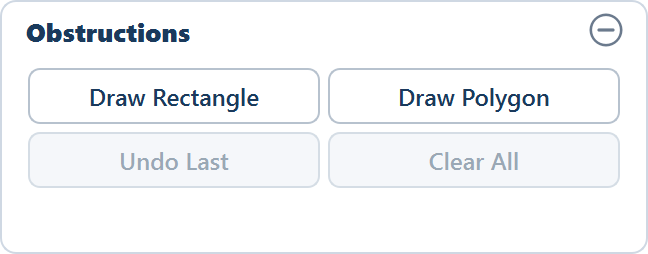
The Obstructions card is the first card of the Tools tab, which is locked until a layout exists — the tools act on the layout already on screen.
| Button | What it does | Hint while armed |
|---|---|---|
| Draw Rectangle | Arms the rectangle tool | "Click and drag on the plot to draw a rectangular obstruction." |
| Draw Polygon | Arms the polygon tool | "Click to add vertices. Double-click or right-click to close." |
| Undo Last | Removes the most recently drawn obstruction | — |
| Clear All | Removes every hand-drawn obstruction | — |
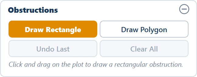
The application calls all of these Obstruction, whatever the ground is actually for. Tables overlapping a hand-drawn obstruction are removed the same way as for one read from the file, and the status line reports the cost at once: "Obstruction added — n tables | m modules | x MWp". After Clear All the status line reads "All roads cleared." — the same thing under an older name.
Drawing an obstruction re-places the inverters but does not re-measure the cables. After a hand-drawn obstruction the String DC cable (m) and AC cable to ICR (m) rows of the Summary view read 0 — while the trench rows keep their old figures — until you click Generate Layout again with Calculate cables on. Generate again before quoting cable lengths.
The obstruction tools in Sketch Mode
Sketch Mode's PLANT OBJECTS group carries two corridor tools, and both work the same way: drag a straight centre-line on the plot, then enter a width.
| Tool | Prompt | Default width | What it does |
|---|---|---|---|
| 🚧 Road | Road width | 5.0 m | Places a road corridor of that width along the line and removes the tables under it |
| ⚡ T-Line | Transmission line corridor | 10.0 m | Draws the red centre-line, records a corridor of that width as a keep-out and removes the tables inside it |
The DRAW group's ╱ Line and ⌒ Polyline ask for a Line width as well: 0 draws a line only, and anything more than 0 makes it a corridor that removes the tables under it — a third way to clear an irregular strip. See Sketch Mode.
A hand-drawn transmission line does not use the Transmission line corridor setback. The width you enter is the whole corridor: the centre-line is buffered by half of it on each side, so the strip cleared of tables is the width you gave, not twice it. So a line you draw and a line of the same route read from the boundary file clear different ground unless you convert one figure into the other. To match a 15 m setback each side, enter a corridor width of 30 m.
What Generate does to hand-drawn obstructions
Hand-drawn obstructions, roads and corridors survive a later Generate Layout. They are collected and handed to the placement as ground to keep clear, so the plant is rebuilt around them. What does not survive is any table you placed or deleted by hand in Sketch Mode — Generate re-places every table from scratch. Draw the obstructions first, generate, and hand-edit individual tables last. The full rule is on Sketch Mode.
What else the usable area governs
Subtracting an obstruction does more than remove tables. The same usable area is the test every other placement decision is made against, which is why a large exclusion changes the plant in ways that are not obvious from the table grid alone:
- Cable routes. Every candidate route is checked against the usable area before it is accepted, so cables detour around water bodies, corridors, obstructions and excluded terrain. A big exclusion in the middle of a plant lengthens the runs around it. See Cable routing and trenches.
- Lightning arrester positions. Only grid positions whose centre falls inside the usable area are kept, so an obstruction thins the arrester grid locally and the coverage is completed afterwards from the nearest valid ground.
- Control room siting. A control room must be fully contained in the usable area, so an exclusion can push a room away from the centre of the group of tables it serves.
- Reported area. Excluded terrain is reported in acres, so you can see how much ground the slope limits took. The Plant area (acres) row of the Summary view is the gross boundary area, so it does not fall as exclusions grow.
What reaches the drawing
Hand-drawn obstructions are exported to the CAD drawing on their own layer, separate from the exclusions that came out of the boundary file. That separation is deliberate and useful: a contractor opening the drawing can see at a glance which ground was excluded by the survey and which ground you decided to keep clear.
| What it is | CAD layer |
|---|---|
| Exclusions from the boundary file | OBSTACLES |
| Water bodies | WATER |
| Hand-drawn obstructions | OBSTRUCTIONS |
| Terrain contour lines | TERRAIN |
See CAD export. The Google Earth export carries the exclusion zones alongside the boundary and the tables; see Google Earth export.
Checking your exclusions before you trust the layout
Generate and look at the gaps
Every gap in the table grid should correspond to something you can name. A gap you cannot account for usually means a feature was classified as something you did not intend.
Switch Satellite on
Satellite in the Layout view's tools puts the aerial photograph behind the layout and shows the real ground. A pond visible on the imagery with tables sitting on it means the polygon is missing from the file or was drawn outside the boundary.
Fix the file, not the layout
A missing exclusion is best fixed by naming and drawing it correctly in the boundary file, then generating again. Hand-drawn obstructions are for what the file genuinely cannot carry.
Where to go next
Boundary file requirements
How each water body, obstruction and line must be named and drawn
How placement works
The usable area, the row sweep, and why a table must fit entirely inside it
Topography
Slope limits, contour data and the ground they exclude
Sketch Mode
The full tool palette for editing a generated layout by hand
Main control room, substations and street lights
Placing the main control room and other structures from the Tools tab on a generated layout, and the perimeter street lights you enable before generating.
Cable routing and trenches
How DC, AC and medium-voltage runs are routed, what the conductor and trench totals mean, where they are reported, and how hand-drawn trenches change later runs.