Sketch Mode
The hand-editing surface — select, move, copy, delete, place tables, arresters, roads, corridors and cable trenches on a generated layout, and recompute the plant totals from your edits.
The generated layout is a starting point. It knows what the boundary file told it: where the fence runs, where the water is, where a transmission line crosses. It does not know that the north-west corner is a spoil heap, that the owner wants two tables left out beside the access gate, or that the trench to the second control room has to follow an existing culvert. Sketch Mode is where you put that knowledge into the design.
Everything you place by hand is part of the plant. A table you add counts towards the module count and the capacity; an arrester you add counts in the arrester row; a road you draw clears the tables under it. The drawing tools — lines, shapes, text, dimensions, measurements — are covered separately in Annotations, measuring and layers, because they change the drawing rather than the plant.
Turning Sketch Mode on and off
Sketch sits in the Layout view's tools, to the right of the view tabs, and starts off. Sketch is a tool of the Layout view: it is available only there, and switching to another view — Summary, Energy, BOM or SLD — switches Sketch off. See Views for the tools row.
Click Sketch and the left column changes. The pinned Generate Layout button gives way to an orange ● Sketch Mode banner with the table count on its right and one button, Exit Sketch Mode — apply edits, recalc totals; the input tabs are replaced by the tool palette; and an orange contextual bar appears above the plot. The status line reads "Sketch Mode ON — select a tool from the left panel."
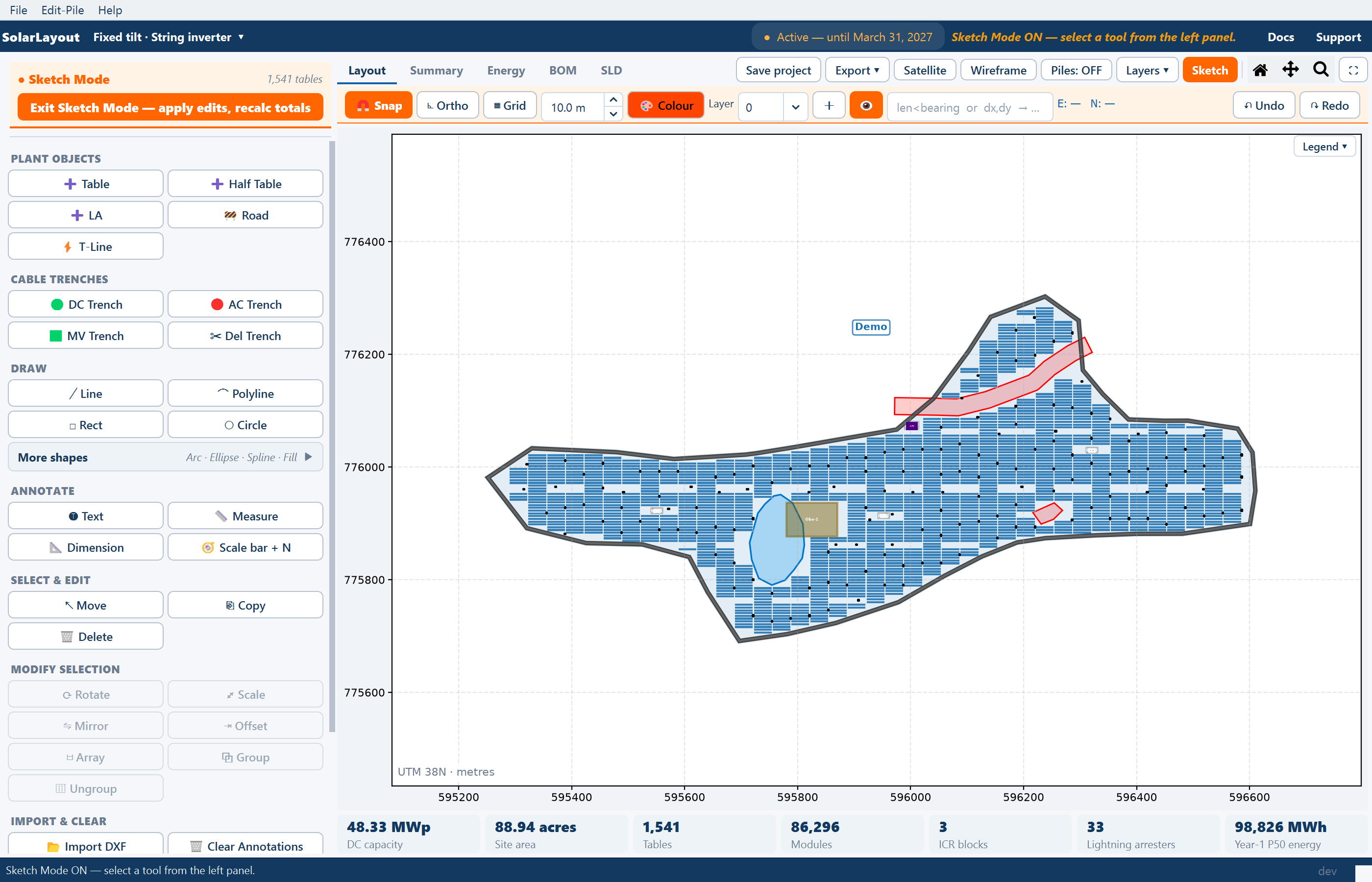
Click Exit Sketch Mode — apply edits, recalc totals and the inputs come back. The status line reads "Sketch Mode OFF — plant totals updated."
The plant totals are recomputed when you leave Sketch Mode, not while you are editing. Module count, capacity and arrester count in the Summary view and the plant chips stay at their pre-edit figures until you exit, so exit before reading the Summary, exporting, or calculating energy.
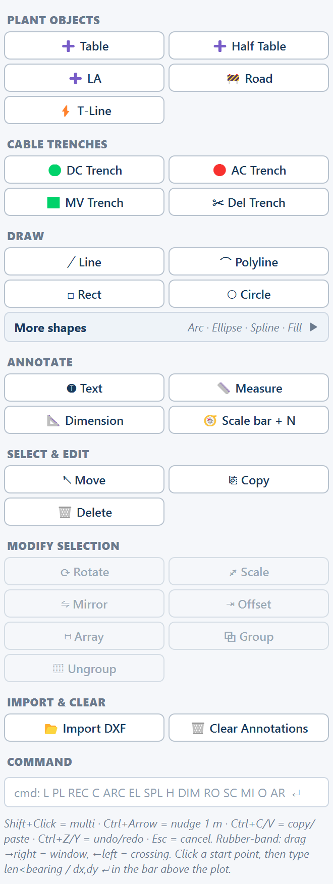
How the palette is organised
The palette is grouped. Pick a tool, act on the plot, and the tool stays armed until you pick another; one tool is active at a time.
| Group | Tools | Covered in |
|---|---|---|
| PLANT OBJECTS | ➕ Table · ➕ Half Table · ➕ LA · 🚧 Road · ⚡ T-Line | this page |
| CABLE TRENCHES | 🟢 DC Trench · 🔴 AC Trench · 🟩 MV Trench · ✂ Del Trench | this page |
| DRAW | ╱ Line · ⌒ Polyline · □ Rect · ○ Circle · More shapes (Arc, Ellipse, Spline, Fill/Zone) | Annotations |
| ANNOTATE | 🅣 Text · 📏 Measure · 📐 Dimension · 🧭 Scale bar + N | Annotations |
| SELECT & EDIT | ↖ Move · ⎘ Copy · 🗑 Delete | this page |
| MODIFY SELECTION | ⟳ Rotate · ⤢ Scale · ⇋ Mirror · ⇥ Offset · ▤ Array · ⧉ Group · ⿲ Ungroup | Annotations |
| IMPORT & CLEAR | 📂 Import DXF · 🗑 Clear Annotations | Annotations |
| COMMAND | a typed command line | Annotations |
On a tracker plant the plant objects read ➕ Tracker and ➕ Half Tracker instead.
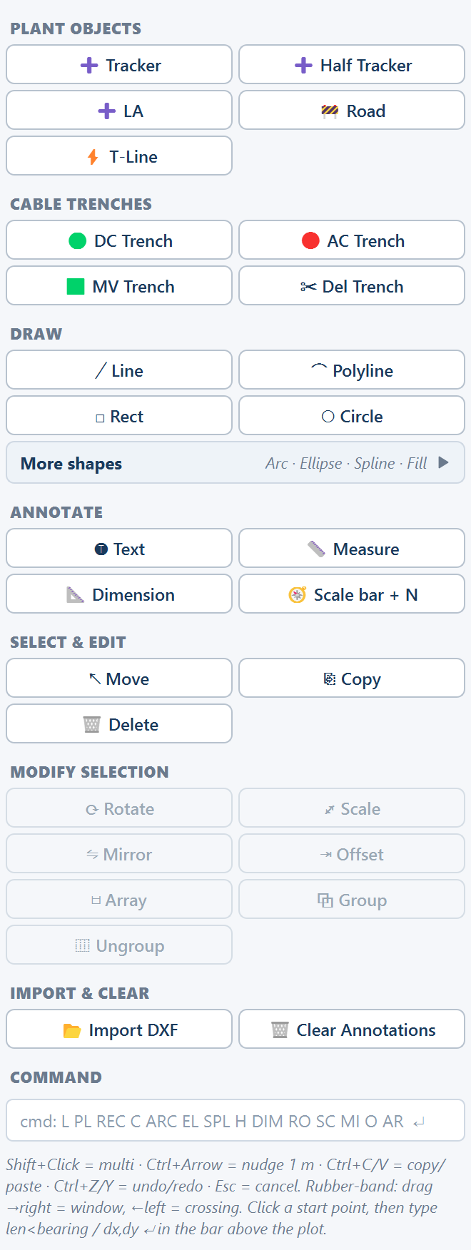
Under the palette a hint summarises the keyboard: "Shift+Click = multi · Ctrl+Arrow = nudge 1 m · Ctrl+C/V = copy/paste · Ctrl+Z/Y = undo/redo · Esc = cancel. Rubber-band: drag →right = window, ←left = crossing. Click a start point, then type len<bearing / dx,dy ↵ in the bar above the plot."
There are no Pan or Zoom buttons in the palette. The mouse wheel zooms at the cursor, and the Home, Pan and Zoom icons in the Layout tools do the rest — but while Pan or Zoom is active a drag on the plot moves the view and the sketch tool ignores it, so click the navigation icon off before you draw.
The contextual bar
The orange strip above the plot holds the drawing aids and the numeric entry. It is present only in Sketch Mode.

| Control | Default | What it does |
|---|---|---|
| 🧲 Snap | on | What you click snaps to nearby geometry — corners, edge midpoints, centres — so a trench meets a control room exactly rather than nearly |
| ⊾ Ortho | off | What you draw is held horizontal or vertical, so a trench cannot pick up an accidental few degrees |
| ▦ Grid + spacing | off, 10.0 m | Draws a reference grid at the spacing you set (0.5–1000 m) |
| 🎨 Colour | orange-red | The stroke colour for what you draw next |
| Layer, +, 👁 | layer 0 | The active annotation layer, a new layer, and show or hide the active layer |
| Numeric entry | — | "len<bearing or dx,dy → Enter": a typed length and direction for the point you are about to place |
| E: — N: — | — | The live cursor position in metres |
| ↶ Undo · ↷ Redo | — | Step back and forward through your edits |
🧲 Snap and ⊾ Ortho are the two to have on before drawing anything you intend to build from. A trench drawn free-hand a degree or two off square looks right on the screen and exports as a drawing nobody can set out from.
The numeric entry takes over from the mouse for the second point of anything:
click a start point, then type 25.4<30 for 25.4 m at a bearing of 30°,
10,5 for 10 m east and 5 m north, or a bare 25.4 for that distance along
the cursor direction — or a radius — and press Enter.
Selecting
↖ Move is the tool you spend most of your time in. It selects, it drags, and it is the tool that repositions anything you have already placed.
| Action | What it does |
|---|---|
| Click an object | Selects it |
| Shift+click another object | Adds it to the selection |
| Drag on empty space to the right | A window rubber band: selects what lies entirely inside the box |
| Drag on empty space to the left | A crossing rubber band: selects everything the box touches |
| Drag any selected object | Moves the whole selection together |
| Ctrl+arrow key | Nudges the selection 1 m in that direction |
| Ctrl+C / Ctrl+V | Copies and pastes the selection |
| Ctrl+Z / Ctrl+Y | Undo and redo |
| Esc | Cancels the tool or clears what it was doing |
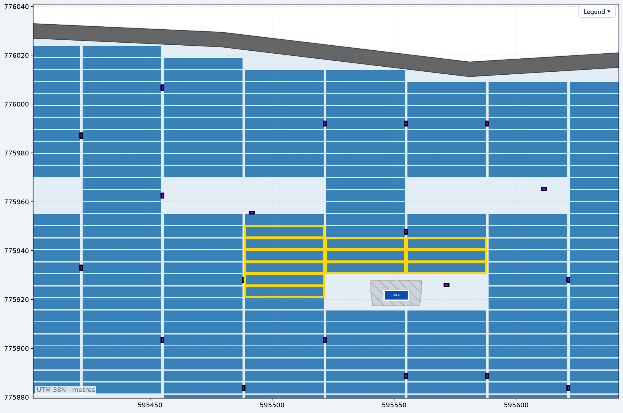
The two rubber bands are the CAD convention and worth learning: a window selection is for picking a clean block of tables without catching the row beside it; a crossing selection is for grabbing every trench that passes through an area. The 1 m nudge is how you work at table scale: pick up a table with the mouse, drop it roughly, then step it into position without touching the mouse again.
The MODIFY SELECTION group — rotate, scale, mirror, offset, array, group, ungroup — is greyed out until there is a selection it can act on. Those tools are described with the drawing tools on Annotations, measuring and layers.
Moving a control room
A control room is not moved with ↖ Move, and does not need Sketch Mode at all. With neither Pan nor Zoom active, click and hold a blue ICR on the plot, drag it, and release. The layout rebuilds around the new position — tables under the new footprint are cleared, and the tables it vacated are available again. A drop where the room does not fit entirely inside the usable area snaps back to where it started. See Inverter control rooms.
Moving, copying and deleting
| Tool | What you do | What happens |
|---|---|---|
| ↖ Move | Select, then drag | The selection moves together |
| ⎘ Copy | Click a table | A copy is placed 5 m east and 5 m north of it |
| 🗑 Delete | Click any object | The object is removed |
To copy several things at once, select them with ↖ Move, then Ctrl+C and Ctrl+V. The offset means a copy lands clear of the original, so you can see it and drag it where it belongs instead of it sitting invisibly on top of what you copied.
🗑 Delete removes on a single click, with no confirmation. ↶ Undo is the way back.
Placing plant objects
Each of these adds a real object to the plant, not a drawing of one.
| Tool | What you do | Effect on the layout |
|---|---|---|
| ➕ Table | Click a position | Places one full MMS table, at the size and orientation set in the table configuration |
| ➕ Half Table | Click a position | Places a half unit — half the east–west modules and capacity; half the north–south strings on a tracker |
| ➕ LA | Click a position | Places a lightning arrester and clears the tables under its footprint |
| 🚧 Road | Drag a straight centre-line, then enter a width | Places a road corridor of that width and removes the tables under it |
| ⚡ T-Line | Drag a straight centre-line, then enter a width | Draws the red centre-line, records the corridor as a keep-out and removes the tables inside it |
A few things follow from that table.
Tables you place are ordinary tables. They take their dimensions from MMS-Table Configuration, so a hand-placed table is the same object the automatic pass places — see Table configuration. A half unit is half the east–west width and carries half the strings, and counts as half a table wherever tables are counted.
Arresters can be added even when the automatic pass placed none. With Place Lightning Arresters left off on the Site tab no arresters are placed and tables fill the whole usable area; ➕ LA is how you add the few you actually want. The footprint that gets cleared is the arrester footprint for your mounting type, which is much larger on a fixed-tilt plant than on a tracker plant. See Lightning arresters.
Roads and transmission lines are drawn as a centre-line with a width. Drag the line, release, and a prompt asks for the width — Road width, default 5.0 m, for a road; Transmission line corridor, default 10.0 m, for a line. The width is the whole corridor: the centre-line is buffered by half of it on each side, so the strip cleared of tables is the width you gave, not twice it.
Transmission line corridor on the Site tab has no part in this. That field applies to the lines read from a boundary file, and it is a setback each side rather than a total width. To clear the same ground as a 15 m setback on a line you draw here, enter a corridor width of 30 m.
A polygon obstruction, a rectangle from the Tools tab, and the main control room and objects are placed from the Tools tab rather than from the palette. See Obstructions and Site equipment.
Cable trenches
Four tools deal with trenches. They are the reason to open Sketch Mode on a plant that is already routed: the automatic route is geometrically sound, but it knows nothing about what is already buried on the site.
| Tool | What you do |
|---|---|
| 🟢 DC Trench | Click vertices, right-click to finish: a DC trench |
| 🔴 AC Trench | Click vertices, right-click to finish: an AC trench |
| 🟩 MV Trench | Click vertices, right-click to finish: a medium-voltage trench |
| ✂ Del Trench | Click any trench — automatic or hand-drawn — to delete it; the untouched trenches stay as the automatic routing |
Trench edits survive the next run. Once you have deleted an automatic trench or drawn one of your own, Generate Layout keeps the current cables instead of re-routing them — the cable follows your trenches — so your route is not overwritten the next time you change an input and generate again. There is no control that hands the cabling back to automatic routing.
What that means for the reported cable and trench lengths — and why trench totals are shorter than conductor totals — is on Cable routing.
An edit from start to finish
Switch Sketch Mode on
Click Sketch in the Layout view's tools. The input tabs are replaced by the tool palette and the contextual bar appears above the plot.
Zoom to the ground you are changing
Roll the mouse wheel over the area, or use Zoom to drag a box around it — then click Zoom off again so your drags reach the sketch tool. Home returns to the whole plant whenever you lose your place.
Switch on the aids the edit needs
🧲 Snap for anything that has to meet existing geometry exactly. ⊾ Ortho for anything that has to run square. ▦ Grid if you want a reference to judge spacing against.
Make the edit
Select with ↖ Move and drag, nudge with Ctrl and the arrow keys, place with ➕ Table or ➕ LA, clear ground with 🚧 Road, reroute with a trench tool. ↶ Undo and ↷ Redo step through anything that went wrong; Esc cancels a half-finished action.
Exit Sketch Mode
Click Exit Sketch Mode — apply edits, recalc totals. The plant totals are recomputed here. Read the module count, capacity and arrester count in the Summary view and confirm they moved the way you expected.
Save the project
Save project in the view header writes the whole session to a .slp file,
sketch edits included, so the edited plant reopens as you left it. See
Projects.
What your edits mean for the numbers
Sketch Mode is not a drawing overlay. The objects you place are counted, and the counting happens when you leave.
| Summary row | What your edits do to it |
|---|---|
| Full tables | Rises and falls with full tables placed and deleted |
| Half tables | Rises and falls with half units placed and deleted |
| Modules | Recomputed from the tables actually present |
| DC capacity (MWp) | Recomputed from the module count and the module wattage |
| Lightning arresters | Recomputed from the arresters actually present |
The full row list is in Summary rows; the plant chips under the view follow the same figures.
Because the totals are recomputed rather than adjusted, the figure you read after leaving Sketch Mode is the figure the whole application then works from. The project report, the Google Earth file and the CAD drawing are all written from the current layout, so they carry your edited plant, not the automatic one — which is the point of editing it. See The project report.
Two consequences worth planning around:
- Calculate energy after editing, not before. Year-one and lifetime generation are computed from the plant capacity. Edit the layout, exit Sketch Mode so the capacity settles, then calculate. See How yield is calculated.
- Rebuild the bill of materials after editing. The materials list is computed from the layout, and ⚙ Rebuild from Layout is what brings your edits into it. See Bill of materials.
What Generate Layout does to your edits
Pressing Generate Layout after editing does a precise thing, and the intuitive guess is wrong in both directions:
- If you are still in Sketch Mode, Generate leaves it first, so the edits are committed rather than lost.
- If the layout was edited, Generate re-places every table, tracker, inverter and control room from scratch into the newly available space. Hand-placed and hand-deleted tables do not survive a Generate.
- The obstructions, roads, corridors and main control room you drew do survive — they are collected and handed to the placement as ground to keep clear, so the plant is rebuilt around your constraints rather than ignoring them.
- Hand-drawn cable trenches also survive, by the separate rule above.
The re-plot is forced back to the aligned grid: Maximize placement is switched off for it, so that pile coordinates stay uniform for construction. If you had it on, the plant you get back is the aligned one, at a lower table count. The status line says "Re-plotting the aligned grid around your sketch edits…" while this happens.
There is no "keep my layout and refresh the numbers" path. So the order of work matters: draw your roads and corridors and place the control room first, generate, and hand-edit individual tables last — anything you do to tables before a Generate is discarded by it.
Where to go next
Annotations, measuring and layers
The drawing, measuring, modify and layer tools, and the typed command line
Pile layout
Define a pile pattern on one table and export the coordinates
Cable routing
What the automatic routes do, and what a hand-drawn trench changes
Obstructions
Every kind of ground kept clear of tables, and how to add your own
Multi-plot sites
One boundary file can hold several separate plant boundaries. Each becomes its own plant, with its own column in the Summary view and its own unit substation.
Annotations, measuring and layers
The drafting side of Sketch Mode — shapes, text, measurements and dimensions, the modify tools, layers and groups, the typed command line, and importing a CAD reference.