The Detailed Project Report
Export ▾ ▸ Export Detailed Project Report writes a Word document — what it contains in order, what the drawing shows, the PDF with piles, and the rest of the Export menu.
The Detailed Project Report is the document the rest of a project is run from:
a written overview and methodology, the design basis, the results, the energy
yield and loss analysis, and then the drawing annexures — the site layout
plan, the design summary, the single-line diagram, the bill of materials and
the energy drawings — in one file. It is a Word document (.docx), so the
narrative can be edited, stamped and issued in your own document system after
export.
It is written from Export ▾ ▸ Export Detailed Project Report. What it contains depends on how much of the design you have completed: the report writes what exists. An energy calculation you have not run is a section that is absent, with no placeholder.
The Export menu
Export ▾ sits beside Save project at the right of the view tabs, in every view, and holds every file export. See Views for the header it belongs to.
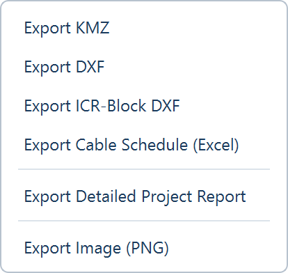
| Item | Produces | Available |
|---|---|---|
| Export KMZ | The Google Earth file — see Google Earth export | After a layout |
| Export DXF | The layered CAD drawing — see CAD drawing export | After a layout |
| Export ICR-Block DXF | One CAD drawing set: sheet 1 the whole plant, then one sheet per ICR block | After a layout |
| Export Cable Schedule (Excel) | A workbook with one sheet per ICR block: the DC strings and the AC or DC-trunk feeders, with recommended conductor sizes | After a layout; cable calculation on for real lengths |
| Export Detailed Project Report | The Word document described on this page | After a layout |
| Export PDF (with Piles) | The PDF report with the pile drawing and coordinates | Only while Piles is on |
| Export Image (PNG) | The plot as it is on screen, as an image file | After a layout |
Every export needs active access, and all are disabled while a run is in progress. The status line confirms each one — "Document exported: …" for the report, "PDF exported: …" for the PDF with piles. See Activating access.
Some exports live elsewhere because they belong to a tool: the bill of materials and the single-line diagram have their own buttons on their tools panels, the pile editor has Export to Excel…, and the Yield tab has Export TMY data CSV.
The document
Choose Export ▾ ▸ Export Detailed Project Report and the Save Word Document dialog asks where to put the file. The document is A3 landscape throughout, with 12 mm margins and the footer "Rensaar Private Limited — Detailed Project Report" on every page.
Exporting is a read of the current session. It adds nothing to the plant and changes nothing, so you can export as often as you like while you work.
The content, in order
| Section | What it carries | Present when |
|---|---|---|
| Cover page | The document's identity | Always |
| Project Overview & Methodology | What the design is and how it was produced | Always |
| Design Basis — Input Parameters | The inputs the layout was produced under | Always |
| Results & Analysis — Output | What the layout produced — the placed plant's figures | Always |
| Energy Yield & Loss Analysis | The yield, the performance ratio and its losses | Only when an energy calculation has been run |
| Site Layout Plan | The engineering drawing of the plant — see below | Always |
| Design Summary | The layout summary, the design parameters and the inverter and cable summary as a drawing sheet | Always |
| Single Line Diagram | Your diagram on its sheet, as you built it in the SLD view | When a diagram exists |
| Bill of Materials | The materials list, paginated (i/n) across as many pages as it needs | Always |
| Energy Yield — Drawings | Two figures when monthly data exists, otherwise one | Only when an energy calculation has been run |
The design basis section is the reason the document matters even when the drawing is the deliverable: it records the inputs the drawing was produced under, so a design issued today can be reconciled with one revisited months later.
The drawing annexures are the same pages the PDF export draws, so the images on this page — taken from the PDF with piles — show what the Word document's annexures look like.
The site layout plan
The layout itself, drawn to fill the sheet, inside a drawing border with a north arrow at the top right, a plant-details table and a title block.
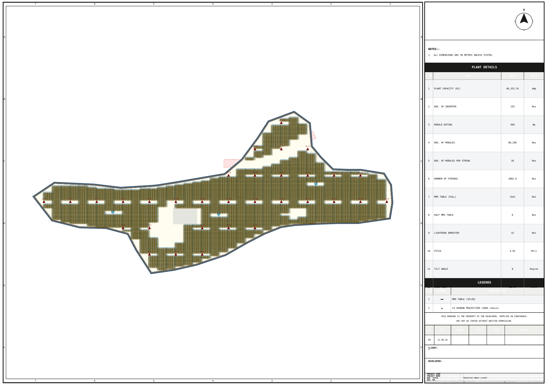
What the drawing shows and hides is fixed, whatever the Layers popover is set to. When the drawing is written the application hides the DC, AC and MV cables and the arrester protection circles, forces the arrester rectangles and their labels visible, draws the page, then puts your on-screen state back as it was. Three consequences:
- Cables are never on the drawing page. A cable drawing comes from the CAD drawing export or the cable schedule, not from the report.
- Arresters always appear, on any run that placed them — including a run where you had the Lightning arresters layer off and saw none on screen. The rectangles are their footprints, and a footprint is buildable information.
- The coverage circles never appear. The protection-radius circles are an on-screen review aid only. If a lightning-protection review needs them, it has to be done on screen. See Lightning arresters.
The design summary
Three blocks on one sheet: the layout summary, the design parameters that produced it, and the inverter and cable summary with its per-ICR breakdown — cable lengths attributed to each inverter control room rather than only totalled for the plant. That is the figure a trenching estimate is built from, because it tells you where the length is, not only how much of it there is. See Cable routing.
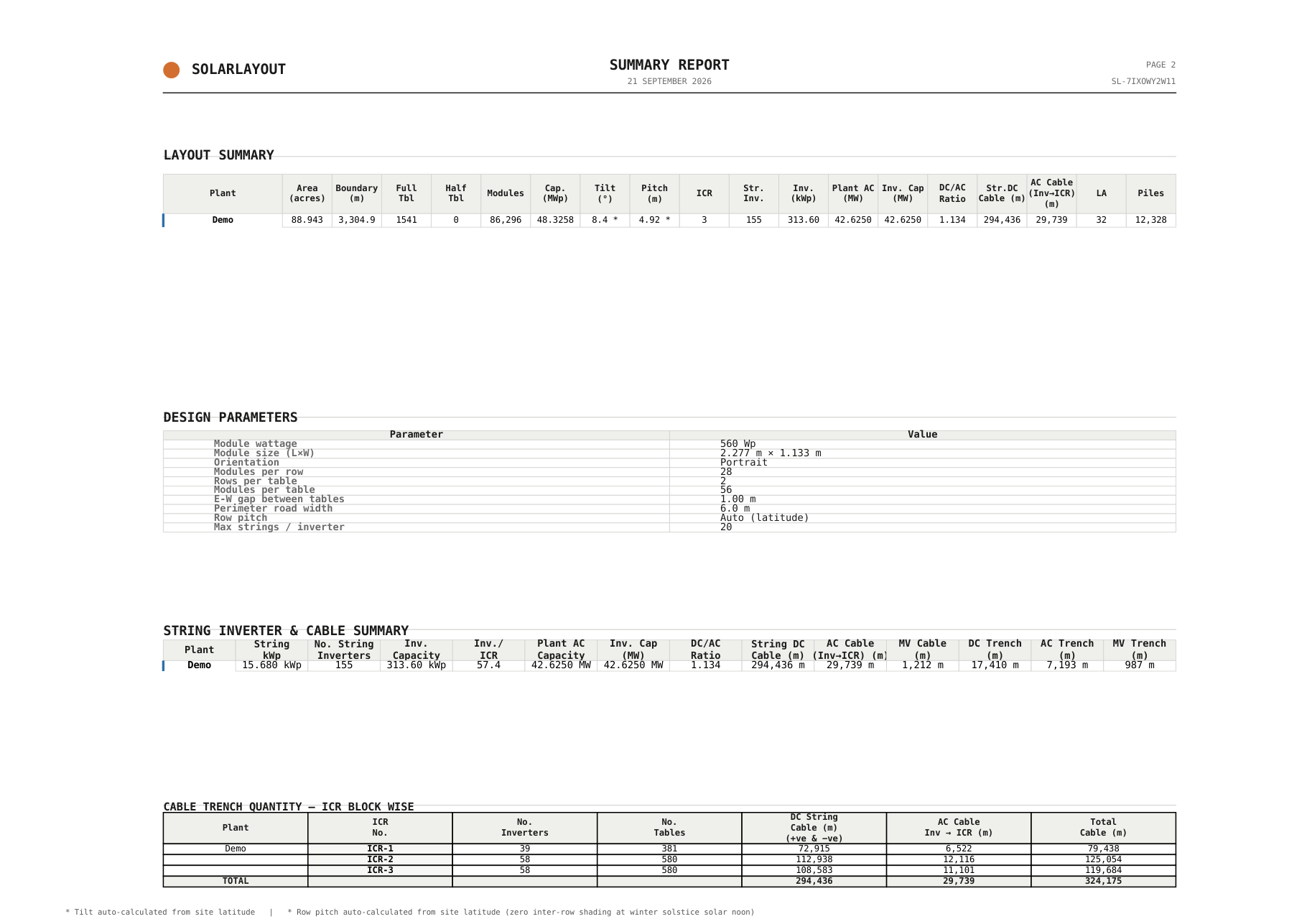
The cable figures exist only if Calculate cables on the Electrical tab was ticked for the run that produced the layout. With cable calculation off, the sheet is still written and the cable entries read as not computed.
The single-line diagram
Your diagram, on its sheet, exactly as you built it in the SLD view. On a large plant the diagram is emitted on a physically larger sheet — A3 to A1 to A0 — while the drawing itself keeps A3 proportions, so a dense diagram stays legible when printed rather than being crushed onto one A3 sheet. See Exporting the diagram.
The bill of materials
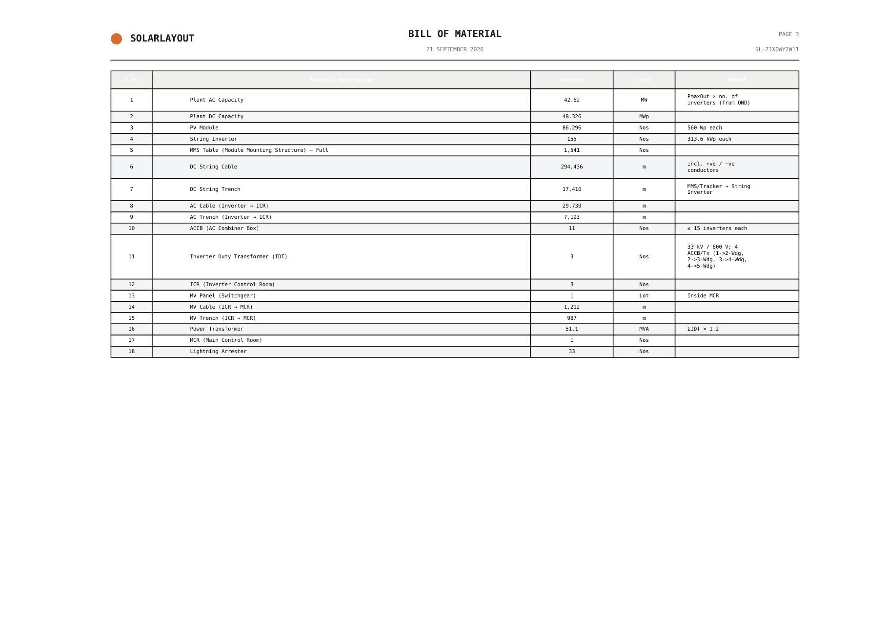
The materials list, paginated across as many pages as it needs; nothing is truncated to fit. What is written is the list as it currently stands in the BOM view, edits included — and, if you have replaced it with a template, the template's rows. See Bill of materials.
The energy sections
Energy Yield & Loss Analysis and Energy Yield — Drawings are present only when an energy calculation has been run. No calculation, no energy sections — that is the only condition, and nothing else gates them. The drawings section carries two figures when monthly data exists and one otherwise. See How yield is calculated.
Export PDF (with Piles)
The report also exists as a PDF, in one case: while the pile overlay is on, Export ▾ gains Export PDF (with Piles). It is the PDF report with the pile pattern drawn on the layout — the pattern you defined on one reference table, stamped onto every table in the plant — and page one is rendered at 300 dpi so that a setting-out crew can resolve individual piles within a table. Expect a large file. Define the pattern first; see Piles.
Every page is A3 landscape, in this order:
| Page | What it carries |
|---|---|
| 1 | The engineering drawing — layout, border, north arrow at the top right, title block and plant-details table — with the piles |
| 2 | The summary: layout summary, design parameters, and the inverter and cable summary with the per-ICR breakdown |
| 3 | The single-line diagram — skipped silently if it cannot be drawn |
| 4… | The bill of materials, paginated |
| last | The energy pages, only when energy was calculated: two pages with monthly data, otherwise one |
A missing diagram page is not a failed export: the rest of the report is still written. If the diagram matters, open the file and confirm the page is there.
The file's own properties name it: the title is "SolarLayout.Desktop Report" and the subject "Automated PV layout summary", so it is identifiable in a document management system without opening it.
Before you export
Each of the steps below adds content to the report. Doing them in this order means one export rather than four.
Generate the layout
Nothing exports without a placed plant. Turn Calculate cables on for the run if you want cable lengths in the summary and the per-ICR breakdown. See Cable routing.
Calculate energy
Calculate Energy on the Yield tab is what makes the energy sections exist. See Weather data.
Build the diagram
Open the SLD tab and choose Automatic, then edit it, or draw it yourself. See Building a diagram from the plant.
Check the materials list
Open the BOM tab, rebuild it once against the finished plant, and correct what needs correcting — because whatever is in it is what prints. See Bill of materials.
Export
Choose Export ▾ ▸ Export Detailed Project Report — and Export PDF (with Piles) as well if you have defined a pile pattern.
What the report does not do
- It does not stamp or certify anything. The title block and the plant-details table identify the drawing; they are not an approval record.
- It does not version itself. Two exports of the same session produce the same document, and nothing tracks revisions for you. Manage that in the file name and in the document after export.
- It is not the CAD deliverable. The drawing page is a picture of the layout, not a layered drawing an engineering team can work in. For that, use the CAD drawing export.
Where to go next
Materials list templates
The built-in reference materials list offered for your design, how to open it in its own window, and the action that replaces the computed list with it.
Google Earth export
The layout written as a Google Earth file — one folder per plant, the summary placemark, what the file leaves out, and how to check the design against real ground.