Building a diagram from the plant
Generate: Automatic draws a starter single-line diagram from the plant's own equipment counts and the materials list's ratings; Full SLD expands it to one feeder per control room.
Generate: Automatic on the SLD TOOLS panel draws a starter single-line diagram — SLD — from the plant you have already laid out. It reads the plant's own equipment counts and the bill of materials' ratings, places the chain from the modules through to the grid, and annotates each block with how many of that item there are and what it is rated at. What you get is a correct-by-count skeleton on the drawing sheet, which you then edit.
It is a starting point, not a finished drawing. The chain it places is the generation-to-grid path; the protection, switching and instrumentation an issued SLD carries is drawing work you do on top of it.
Before you run it
The automatic build reads the plant as it stands at the moment you use it, so the plant has to exist first.
Generate the layout
The equipment counts come from the placed plant — the inverters or string monitoring boxes, and the control rooms they feed. With no layout there is nothing to count. See Your first layout.
A generated layout is the whole prerequisite. The ratings come from the bill of materials, which is computed from the layout alone, so no energy calculation is needed — running the yield calculation first adds nothing to the diagram.
Open the SLD view and choose Automatic
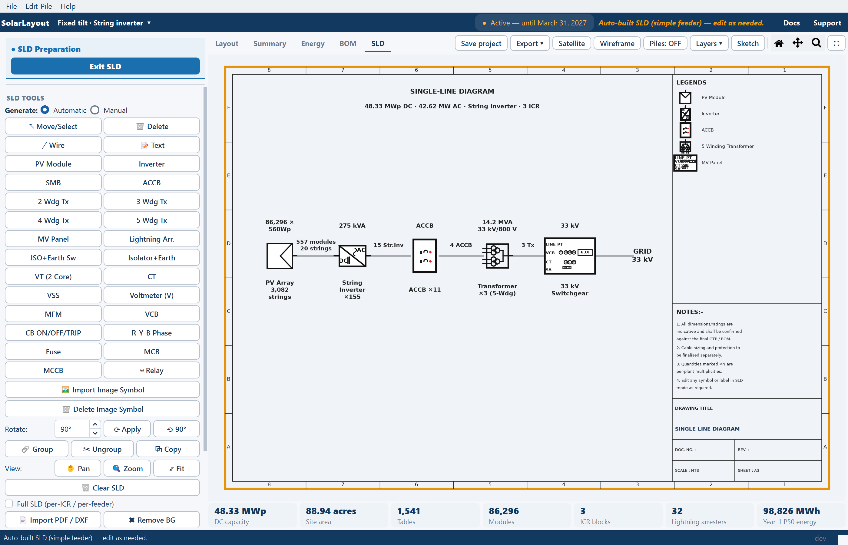
Click the SLD tab (Ctrl+5). Nothing is drawn yet: the Generate: row at the top of the tools panel offers Automatic and Manual. Choose Automatic. The chain is drawn on the sheet and the status line reads "Auto-built SLD (simple feeder) — edit as needed."
The automatic build reads the plant at the moment you run it. If the layout changes afterwards, choose Automatic again so that the chain and the plant describe each other — and expect the sheet to be rebuilt, not merged with your edits.
The chain it draws
Which chain you get follows the inverter choice made at launch, because the two topologies convert the DC in different places. See Choosing a design mode.
PV → String Inverter (×N) → ACCB (×n) → Transformer → MV Panel → Grid| Stage | What it is |
|---|---|
| PV | The module field feeding the inverters |
| String Inverter (×N) | The string inverters placed across the plant, each converting DC to AC where it stands. N is how many the layout placed |
| ACCB (×n) | The AC combiner boxes the inverters land on. n follows from the inverter count and the inverters-per-box rule |
| Transformer | The machine taking the collected AC output up to medium voltage |
| MV Panel | The medium-voltage switchgear the transformer feeds |
| Grid | The outgoing connection |
The AC leg is what distinguishes this chain: conversion happens out in the field, so what arrives at the combiner box is already AC.
Both chains end the same way, and both are drawn along a horizontal bus — which is why the inverter and every transformer are placed already rotated to line up with it. See Building the single-line diagram.
Simple feeder or full SLD
The build has two forms, switched by the Full SLD (per-ICR / per-feeder) checkbox on the tools panel. It applies to the automatic build only.
| Full SLD | What is drawn |
|---|---|
| Off — the simple feeder | One annotated feeder, with each block carrying a ×N multiplicity for how many of it the plant holds |
| On | Parallel feeders, one per inverter control room, converging on per-ICR transformers |
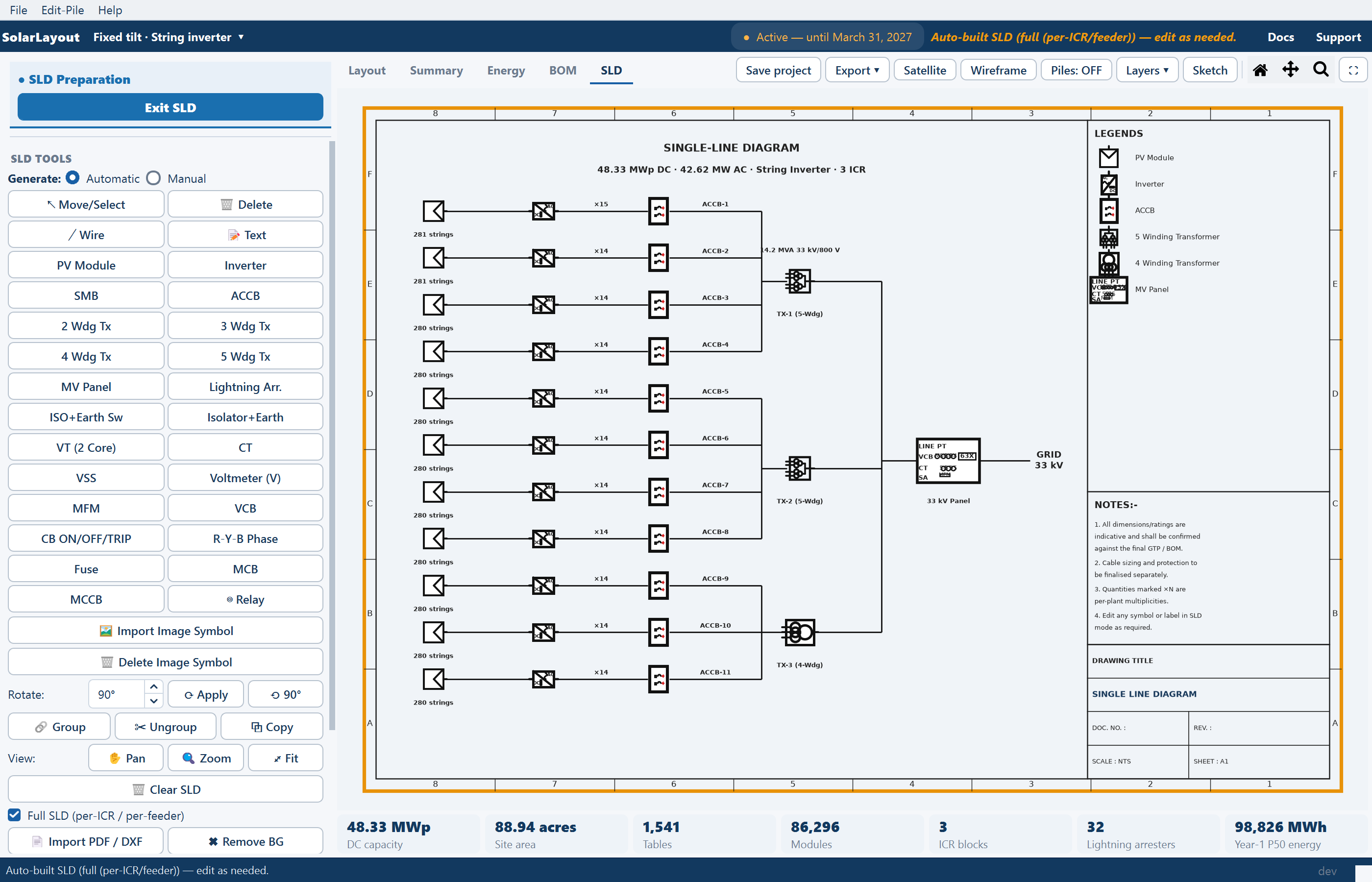
Ticking or unticking the box rebuilds the diagram in the other form, so choose the form before you start editing. The simple feeder is the readable one on a plant with dozens of machines; the full form is the one that shows every control room's feeder separately. A large plant drawn this way is where the physical paper size grows — see the sheet notes on Building the single-line diagram.
The topology rules it applies
Three rules decide how many combiner boxes and transformers the chain carries:
| Rule | Value |
|---|---|
| Inverters per AC combiner box | 15 |
| AC combiner boxes per inverter duty transformer | 4 |
| Maximum inverter duty transformer capacity | 17.2 MVA |
Read them as a cascade. Inverters are grouped fifteen to a box; boxes are grouped four to a transformer; and a transformer is capped at 17.2 MVA, so a grouping that would exceed the cap is split rather than carried.
These are the same rules the bill of materials uses. The diagram's box and transformer counts therefore agree with the quantities in the materials list for the same plant — the two are not derived independently, so there is no reconciliation to do between them. See Bill of materials.
If your own scheme groups equipment differently — a different number of inverters per box, or a transformer size you have already fixed with a supplier — the chain will not match it. Edit the drawing to your scheme, and expect the materials list to still show the rule-based quantities.
What the annotations mean
Each block on the chain is annotated with two things:
- A multiplicity, written as
×N— how many of that item the plant carries. One inverter symbol carrying a multiplicity stands for every inverter in the plant, drawn once. That is normal single-line practice, and it is what keeps the sheet readable on a plant with dozens of machines. - A rating, taken from the bill of materials for that item.
Both are put on the sheet by the build rather than typed by you. Where one is wrong — a rating that does not match the machine you are buying, or a count you have since revised — correct it on the sheet with the 📝 Text tool.
What to do next
Treat the result as a first draft, in this order:
Check every rating
The ratings come from the materials list, which is itself derived from the layout. Read each one against the equipment you are actually procuring, and correct the annotation where it differs.
Add what the rules do not cover
The chain carries the generation-to-grid path. Isolators, breakers other than the combiner boxes on the chain, instrument transformers, meters, relays, arresters and phase indication are all yours to place from the palette and wire in. See Symbol reference.
Fill in the legend, the notes and the title block
All three ship blank — no company name, no project name, no drawing number. Complete them with 📝 Text.
Fit and export
Use ⤢ Fit to see the whole sheet, then export it from the tools panel, or leave it to be carried into the Detailed Project Report as the report's diagram page. See Exporting the diagram.
Where to go next
Symbol reference
The symbols to add on top of the automatically built chain
Building the single-line diagram
The sheet, the tools, and editing what the build placed
Bill of materials
Where the ratings and the matching quantities come from
Exporting the diagram
The report page, a standalone PDF, and the CAD file
Symbol reference
Every symbol the SLD TOOLS palette carries, grouped by what it does — generation, AC distribution, transformers, protection and instrumentation.
Importing diagrams and custom symbols
Bringing an existing diagram in as a background to draw over, and tracing your own image into a vector symbol that exports to CAD as real geometry.