Annotations, measuring and layers
The drafting side of Sketch Mode — shapes, text, measurements and dimensions, the modify tools, layers and groups, the typed command line, and importing a CAD reference.
A layout is a set of positions. A drawing is a layout somebody can build from: it carries the dimensions that matter, the labels that name things, a north arrow, a scale, and the notes that explain the parts a plan view cannot show. The annotation tools in Sketch Mode are how you turn the first into the second without leaving the application.
Annotations are drawing content. They do not clear ground, they are not counted in the plant totals, and they never change the capacity — that is the difference between them and the plant objects on Sketch Mode. What they do is travel: onto the screen, and into the exported CAD drawing on a layer of their own. The one exception is a line drawn with a width, below, which does clear ground.
Getting to the tools
Click Sketch in the Layout view's tools. Every tool on this page is in the same palette as the editing tools — the DRAW, ANNOTATE, MODIFY SELECTION, IMPORT & CLEAR and COMMAND groups — and one tool is active at a time.
Each element you draw is created on the active layer, in the current stroke colour, and can be put into a group. The default stroke is an orange-red, 1.5 pt wide; 🎨 Colour on the contextual bar above the plot changes it for what you draw next.
Drawing shapes
The DRAW group shows four tools, with four more behind the More shapes expander. The multi-point tools all end the same way — right-click or double-click.
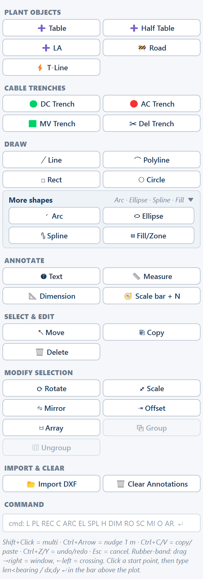
| Tool | What you do |
|---|---|
| ╱ Line | Click and drag a straight line, then answer the Line width prompt |
| ⌒ Polyline | Click each vertex; right-click to finish; then answer the Line width prompt |
| □ Rect | Click and drag a rectangle |
| ○ Circle | Click the centre, then drag the radius |
| ◜ Arc (More shapes) | Click the start, then the end, then a point on the arc |
| ⬭ Ellipse (More shapes) | Click and drag a bounding box |
| ∿ Spline (More shapes) | Click the fit points; right-click or double-click to finish |
| ▨ Fill/Zone (More shapes) | Click the points of the zone; right-click or double-click to finish |
Three of those deserve a note.
╱ Line and ⌒ Polyline ask for a width. Enter 0 and you get a line only — an annotation like any other. Enter more than 0 and the line becomes a corridor of that width that removes the tables under it, the same model as the 🚧 Road tool. It is the way to clear an irregular strip — a drain, a track that bends — that a straight road centre-line cannot describe.
◜ Arc takes three clicks in a specific order — start, end, then a point the arc must pass through. The arc is not drawn until the third click, so nothing appears to happen after the first two.
▨ Fill/Zone is a filled polygon of its own. Click its corners and finish with a right-click. It is the tool for marking out a phase, a contractor's work area, or a land parcel that is not an exclusion.
Switch ⊾ Ortho on before drawing anything that has to run square, and leave 🧲 Snap on — it is on by default — for anything that has to meet existing geometry exactly.
Typing a point instead of clicking it
The numeric entry on the contextual bar replaces the second click of any tool. Click a start point, then type into the bar and press Enter:
| You type | You get |
|---|---|
25.4<30 | 25.4 m at a bearing of 30° |
10,5 | 10 m east and 5 m north of the start point |
25.4 | 25.4 m along the cursor direction — or a radius, for a circle |
That is how a boundary offset, a fence setback or a trench of a known length goes onto the drawing at its real dimension rather than at a guess.
Text labels
🅣 Text places a label. Click where the label goes and an Add text prompt takes the text — it accepts more than one line, so a note does not have to be a single long string — and the label sits at that position on the plot.
To reposition a label, switch to ↖ Move and drag it. Labels select, move and delete like any other element.
Text is the tool that carries the things the geometry cannot say: a plot name, a phase number, an access route, a caveat about a survey. Write them as they should read on the printed drawing, because that is where they end up.
Measuring
📏 Measure answers a question; it does not add anything to the drawing and nothing it shows is saved.
| Points you click | What you get |
|---|---|
| Two | The distance between them and the bearing from the first to the second |
| Three or more, then double-click or right-click | The area and perimeter of the shape, with the angle at each vertex |
Each click snaps to corners, edge midpoints and centres of what is already on the plot, so a measurement between two tables is between the tables, not between two points near them. Esc clears the measurement.
The bearing on a two-point measurement is what makes this useful for setting out — it is the number you hand to a surveyor along with the distance. The area is for the questions a plan view raises: how much ground a phase covers, or the size of the parcel a fence encloses.
All internal geometry is in metres, projected to the site's local UTM zone, so a measurement is a ground distance, not a screen distance. Zooming does not change it.
Dimensions
📐 Dimension places a dimension that stays on the drawing: click and drag between the two points, or click a start point and then type a length into the numeric entry. It is saved with the project, redrawn with the plot and exported to the CAD drawing.
The distinction between the two tools is worth being deliberate about:
| Aspect | 📏 Measure | 📐 Dimension |
|---|---|---|
| Purpose | Check a distance now | Record a distance for someone else |
| Stays on the drawing | No | Yes |
| Goes into the exported drawing | No | Yes |
Dimension the things a construction team would otherwise have to derive: row pitch, the gap between table runs, the setback from the fence to the first row, the clearance around a control room. Those are the numbers that get queried on site.
Modifying a selection
The MODIFY SELECTION group acts on whatever is currently selected with ↖ Move, and stays greyed out until a selection exists that it can act on.
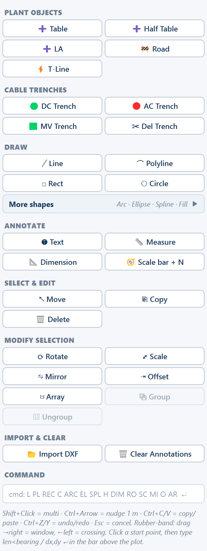
| Tool | What it asks | What it does |
|---|---|---|
| ⟳ Rotate | An angle, in degrees clockwise | Turns the selection |
| ⤢ Scale | A factor | Enlarges or shrinks the selection |
| ⇋ Mirror | Left↔right or top↔bottom | Flips the selection |
| ⇥ Offset | A perpendicular distance | Places a parallel copy of a line or shape at that distance |
| ▤ Array | A rectangular or polar pattern | Repeats the selection in a grid or around a centre |
| ⧉ Group | — | Groups the selected annotations so they select and move together; needs two or more annotations selected |
| ⿲ Ungroup | — | Breaks the group apart again |
A group moves as one. Select the elements that belong together — a dimension and the label that explains it, an outline and its fill — group them, and from then on ↖ Move picks up the whole thing. Ungroup when you need to change one part. Groups are independent of layers: an element carries a layer and, optionally, a group, and grouping elements does not move them onto a layer of their own.
Layers
Layers control what is visible on screen. The three layer controls sit on the contextual bar above the plot, not in the palette:
| Control | What it does |
|---|---|
| Layer | The active layer — everything you draw goes onto it. Starts at 0 |
| + | Creates a new layer and makes it active |
| 👁 | Shows or hides the active layer |
Create the layer first and then draw. The habit that pays off is one layer per audience — dimensions on one, civil notes on another, a client's mark-ups on a third — because then you can show one and hide the rest instead of deleting anything.
Your own layers stay in the application
The exported CAD drawing separates the plant from the annotations. Boundaries,
tables, control rooms, inverters, cables and trenches each land on their own
layer; every Sketch Mode annotation lands on the single SKETCH layer,
whatever in-application layer it was drawn on, and labels and text land on
ANNOTATIONS. Three layers of working come out as one.
That separation is still what makes the drawing usable by somebody else. A
civil contractor opens the file, switches off SKETCH and ANNOTATIONS, and
has a clean plan of the plant with none of your working on it. But layers you
create with + are a tool for the screen — for hiding your own working to
read the layout underneath, and for keeping a client's mark-ups apart from your
dimensions — not a way to hand structured layers to somebody else. If the
recipient needs that separation in CAD, it has to be rebuilt there. See
CAD export.
Bringing an existing drawing in
📂 Import DXF brings a CAD drawing onto the canvas so you can draw against it — an existing site plan, a survey, a road alignment, a neighbouring developer's drawing. It is a reference to work over, not an input to the layout: importing a drawing does not create obstructions and does not move any tables.
The drawing's coordinates are read as they are, in project metres. Nothing is scaled, re-centred, or fitted to the plant, so the drawing has to already be in the same coordinate system as the project.
Import a drawing that is not georeferenced to the site — one drawn around a local origin, say — and it will not appear over the plant. It lands wherever its own coordinates put it, usually far enough away to be off the visible canvas altogether. Click Home in the Layout tools to fit the view and you will see how far out it went.
Seven entity types come across: lines, polylines, circles, arcs, ellipses, splines and text. Anything else in the file is skipped. The elements land on the active layer and are editable like anything you drew, and the status line reports how many came in and onto which layer — so pick or create that layer before importing.
To turn something in an imported drawing into ground the layout must avoid, draw it as a road, a corridor or an obstruction. See Obstructions.
The scale bar and north arrow
🧭 Scale bar + N switches a metric scale bar and a north arrow on and off together. They belong on anything that leaves the application as a picture — Export ▾ Export Image (PNG), a drawing handed to somebody who was not part of the design.
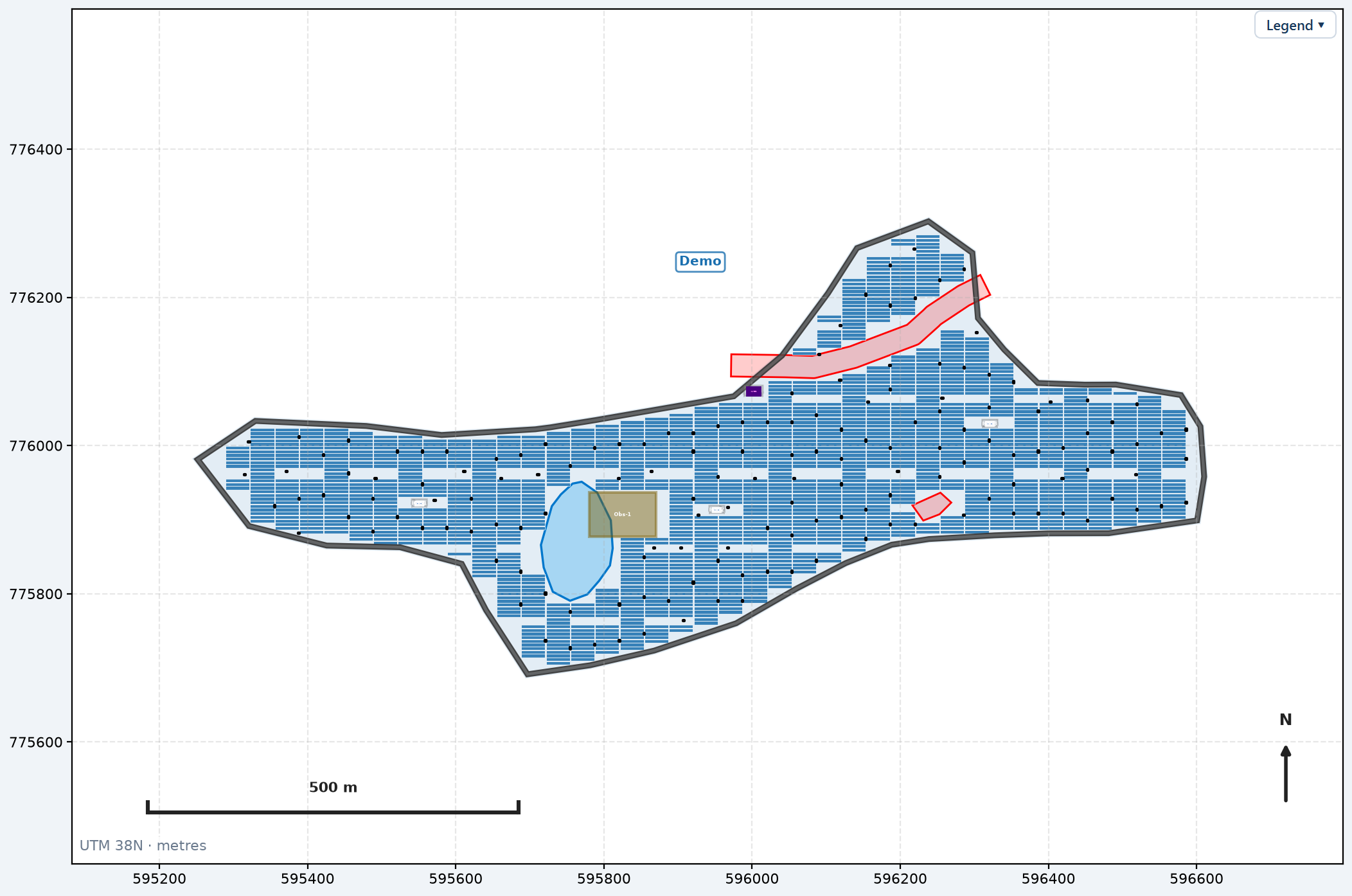
The project report draws its own north arrow and title block on the site layout plan, so you do not need this for the report itself. See The project report.
Clearing annotations
🗑 Clear Annotations removes the annotation elements in one action.
🗑 Clear Annotations clears the drawing content wholesale, not only the selection. If the aim is only to get annotations out of the way — to read the layout underneath, or to take a clean capture — hide the layer with 👁 instead, and everything is still there when you show it again.
Plant objects are not annotations, so clearing annotations does not remove tables, arresters, roads or trenches. Those are deleted with 🗑 Delete and ✂ Del Trench.
Working from the keyboard
The COMMAND line at the foot of the palette takes typed aliases. If you draft in CAD every day, it is faster than finding a button: type the alias, press Enter, and the tool is armed. Its placeholder lists them: "cmd: L PL REC C ARC EL SPL H DIM RO SC MI O AR ↵".
| Type | Tool |
|---|---|
L | ╱ Line |
PL | ⌒ Polyline |
REC | □ Rect |
C | ○ Circle |
ARC | ◜ Arc |
EL | ⬭ Ellipse |
SPL | ∿ Spline |
H | ▨ Fill/Zone |
DIM | 📐 Dimension |
T | 🅣 Text |
RO | ⟳ Rotate |
SC | ⤢ Scale |
MI | ⇋ Mirror |
O | ⇥ Offset |
AR | ▤ Array |
U | ↶ Undo |
RE | ↷ Redo |
M | 📏 Measure |
S | ↖ Move, for selecting |
The aliases are the ones a CAD user already has in their fingers, so a drafting
session runs at keyboard speed: PL, click the vertices, right-click, DIM,
drag, T, type the note. The full keyboard reference is in
Keyboard and commands.
What to put on a drawing you hand over
The tools are general, so the useful question is which of them a recipient actually needs. This is the set that answers the questions a design drawing gets asked on site.
| Add | With | So that |
|---|---|---|
| Row pitch, and the gap between table runs | 📐 Dimension | Nobody sets out spacing from a scaled print |
| The setback from the fence to the first row | 📐 Dimension | The perimeter road width is visible as a built dimension, not an assumption |
| Clearance around each control room | 📐 Dimension | The access the equipment needs is on the drawing |
| Plot and phase names | 🅣 Text | A multi-plot site can be discussed plot by plot |
| Access routes and gates | ⌒ Polyline at width 0, plus 🅣 Text | The route to each part of the plant is agreed before mobilisation |
| Contractor or phase work areas | ▨ Fill/Zone | Two teams on site know where their boundary is |
| Scale and orientation | 🧭 Scale bar + N | The drawing survives being printed, cropped or pasted |
Keep each of those on a layer that says who it is for, and the same drawing serves the client, the civil contractor and the electrical contractor without being redrawn three times.
Where to go next
Sketch Mode
The hand-editing surface — select, move, copy, delete, place tables, arresters, roads, corridors and cable trenches on a generated layout, and recompute the plant totals from your edits.
Pile layout
Define a pile pattern on one reference table in the Pile layout window, stamp it onto every table in the plant, and export the coordinates a setting-out team works from.