String sizing
The String sizing window opened from the Size… button — the three voltage limits that bound the number of modules in series, what you enter, and where the result lands.
A string's length is a voltage decision. Wire too many modules in series and the string's open-circuit voltage exceeds what the plant's insulation and equipment are rated for; wire too few and the string spends the hottest, brightest hours below the voltage the inverter can track. The String sizing window computes the range of module counts that satisfies both ends of that problem for your module, your inverter and your site's temperature extremes, and lets you pick from the range.
The count you settle on is not only electrical. It sets how many modules sit in a row, and therefore the physical size of the table — which sets the row pitch, the ground coverage ratio and, in the end, how much capacity fits on the site.
Opening the calculator
The window opens from a Size… button — its tooltip reads Open the string-sizing calculator — in two places:
| Where | Beside |
|---|---|
| The Array tab | Modules per row on the MMS-Table Configuration card (fixed tilt), or Modules per string (N–S) on the Tracker Configuration card (tracker) |
| The Simulation with AC Capacity window | Modules per string in its TARGET card |
It needs two files, because the constraint has two sides:
| Input | What it supplies |
|---|---|
| The module file | The module's open-circuit and maximum-power-point voltages, how they move with temperature, and its nominal operating cell temperature |
| The inverter file | The machine's tracking voltage window — the range of DC voltage over which it can hold the maximum power point (MPPT — maximum power point tracking) |
If either is missing, Size… says so instead of opening the window:
| Message | What it means |
|---|---|
| Module PAN file required — String sizing reads the module voltages from a PAN file. Use Load .PAN under Module Specifications, then choose Size… again. | Load the module file on the Array tab first. See Module specifications |
| Inverter OND file required — String sizing needs the inverter's MPPT window from an OND file. Select it now. | The file dialog for the inverter file opens at once; pick one and the window follows. See Inverter settings |
| MPPT range missing — The OND file has no MPPT voltage range, so the string length cannot be sized automatically. Enter it manually. | The inverter file carries no tracking window, so there is nothing to fit a string inside. Enter the module counts by hand, or load a file for the same machine that declares the range |
The three constraints
Write N for the number of modules in series, Voc for a module's open-circuit voltage and Vmp for its voltage at the maximum power point. Both fall as temperature rises and rise as temperature falls, because a crystalline silicon module's voltage temperature coefficient is negative. That one fact is why the cold end of the year sets the maximum string length and the hot end sets the minimum. Every constraint is evaluated at the cell temperature, not the air temperature.
| # | Constraint | Bounds | Protects against |
|---|---|---|---|
| 1 | N × Voc(cold) ≤ Vsys | Maximum N | Exceeding the plant's DC system voltage rating |
| 2 | N × Vmp(cold) ≤ Vmppt,max | Maximum N | An operating point above the inverter's tracking window |
| 3 | N × Vmp(hot) ≥ Vmppt,min | Minimum N | An operating point below the inverter's tracking window |
cold is the coldest cell temperature the site sees; hot is the hottest. Vsys is the DC system voltage class. Vmppt,max and Vmppt,min are the two ends of the inverter's tracking window.
1 — Open-circuit voltage on the coldest day
N × Voc(cold) ≤ Vsys
This is the hard limit, and the only one of the three whose violation is a safety matter rather than a yield matter. Cables, connectors, fuses, DC switchgear and the inverter's DC input are all rated for a system voltage class. The worst case for a string is not full sun — it is open circuit on the coldest morning: no current flowing, so the string sits at Voc, and Voc at its maximum because the modules are at their coldest. That happens before the inverter starts in the morning, and again any time the DC side is isolated during a cold spell.
Size against the coldest temperature the site will ever see, not the average winter minimum. Exceeding the class once is enough to matter.
2 — Operating voltage on the coldest day
N × Vmp(cold) ≤ Vmppt,max
Cold and bright at once is the demanding case: the string is generating, so it sits at Vmp rather than Voc, but Vmp is at its highest because the cells are cold. On a clear cold morning a string sized only against constraint 1 can be generating above the top of the inverter's tracking window, and the inverter cannot hold the maximum power point there. It limits, it clips, or it waits — and the loss falls on exactly the hours a cold-climate plant earns most.
Constraints 1 and 2 both bound the maximum, and which one binds depends on the machine. The smaller of the two, rounded down, is the largest string you may build.
3 — Operating voltage on the hottest day
N × Vmp(hot) ≥ Vmppt,min
The opposite end. Cell temperature on a hot afternoon runs well above ambient — a module in open-rack mounting under full irradiance is far hotter than the air around it, which is why the window asks for an irradiance and a cell-temperature model rather than only for air temperature. Vmp at that temperature is the lowest the string ever produces while generating. Fall below the bottom of the tracking window and the inverter loses the ability to track; the yield lost is again at the hours of highest irradiance, and it recurs every hot afternoon for the life of the plant.
This constraint sets the minimum string length, rounded up.
Reading the range
Together the three give a closed range: the minimum from constraint 3, the maximum from whichever of constraints 1 and 2 binds first. Any N inside the range is electrically valid, and the choice between them is a design preference — a longer string means fewer strings, fewer string cables and less DC copper for the same capacity; a shorter string means more parallel paths and finer granularity when you fit strings to an inverter.
If the minimum comes out above the maximum, no string length satisfies all three, and that module and that inverter cannot be paired at that system voltage class. Change one of the three. A higher system voltage class, a machine with a wider tracking window, or temperature extremes that reflect the site rather than a worst case borrowed from elsewhere are the three levers, in that order of practicality.
The window
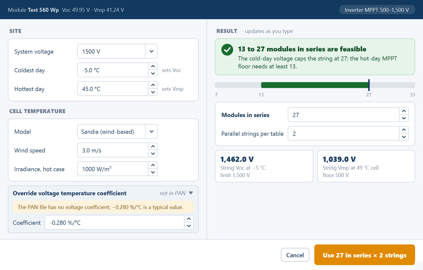
A strip across the top records what the calculation starts from: the module's maker, model and wattage; its Voc and Vmp; and an Inverter MPPT min–max V chip for the tracking window. The inputs are on the left in two cards, the result on the right, and every figure on the right recalculates as you type.
SITE
| Field | Default | Range | What it does |
|---|---|---|---|
| System voltage | 1500 V | 1000, 1100, 1500 or 2000 V, and editable | The plant's DC system voltage class — Vsys in constraint 1 |
| Coldest day | −5.0 °C | −40–40 °C | The cold case, as air temperature; the hint reads sets Voc. Drives the maximum string length |
| Hottest day | 45.0 °C | 10–70 °C | The hot case, as air temperature; the hint reads sets Vmp. Drives the minimum |
CELL TEMPERATURE
| Field | Default | Range | What it does |
|---|---|---|---|
| Model | Sandia (wind-based) | Sandia (wind-based) or NOCT model | How air temperature is converted to cell temperature |
| Wind speed | 3.0 m/s | 0–15 m/s | Convective cooling. Shown for the Sandia model only |
| NOCT | From the module file | 30–60 °C | Nominal operating cell temperature, shown for the NOCT model; the hint reads typ. 42–48, or estimated when the file carries no value |
| Irradiance, hot case | 1000 W/m² | 100–1200 W/m² | The irradiance the hot cell temperature is computed at |
Cell temperature, not air temperature, is what moves the voltages, and Model decides how one is derived from the other. Both relations add a rise to the air temperature that grows with irradiance:
NOCT model:   T cell = T air + ((NOCT − 20) / 800) × G

Sandia model: T cell = T air + G × (0.0126 − 0.0029 × wind speed)
The Sandia relation is the shipped choice and the one that responds to wind, so it suits a site with a known wind record. The NOCT relation depends only on the module and the irradiance, which makes it the safer choice when the wind figure would be a guess. On the shipped hot case both are evaluated at 1000 W/m², so the rise they add is substantial — which is the point of the field. Sizing constraint 3 against 45 °C air temperature alone would credit the string with a higher Vmp than it ever reaches in service, understate the minimum length, and put the array below the tracking window on exactly the afternoons it was sized for.
The voltage temperature coefficient
Under the two cards, an expander headed Override voltage temperature coefficient carries the coefficient the voltages are moved by. Its summary reads the file's value — for example −0.280 %/°C from PAN — or not in PAN when the module file carries none, in which case the expander opens by itself.
| Field | Default | Range | What it does |
|---|---|---|---|
| Coefficient | The module file's Voc coefficient, otherwise −0.28 %/°C | −1.0 to −0.05 %/°C | Applied to both Voc and Vmp when moving them from 25 °C to the cold and hot cell temperatures |
RESULT
The right-hand side is headed RESULT · updates as you type. From the top, it holds a verdict banner, a range bar, the two pick fields and two tiles.
The verdict banner. A feasible pairing reads, for example, 13 to 27 modules in series are feasible — or Only 27 modules in series are feasible when the range is a single count — with a detail line naming the binding constraint at each end, such as The cold-day voltage caps the string at 27; the hot-day MPPT floor needs at least 13. That detail is the line to read: if the cap is named as the cold-day voltage, a wider tracking window buys you nothing and a higher system voltage class buys you everything — and the other way round if the cap is the top of the tracking window. An infeasible pairing reads No string length fits these limits with No feasible string length. Raise the system voltage or check the temperatures.; a file without a tracking window reads The string length cannot be sized.
The range bar shows the feasible span of series counts and where your pick sits on it.
The pick is two fields, named for the mounting:
| Fixed tilt | Tracker | Range | What it means |
|---|---|---|---|
| Modules in series | Modules per string | 1–200 | The string length, chosen from inside the feasible range |
| Parallel strings per table | Strings per tracker | 1–200 | How many of those strings one table or tracker unit carries |
Until you edit it, the series count follows the largest feasible string. A pick outside the range explains itself under the banner — Over 1,500 V on the coldest day. Choose 27 or fewer. or Below the 850 V MPPT floor on the hottest day. Choose 13 or more. — with the limits and counts from your own files.
The two tiles are String Voc at −5 °C — at your coldest-day figure — with the system voltage under it (limit 1,500 V, or over the 1,500 V limit), and String Vmp at … °C cell — the hot cell temperature the model produced — with the tracking floor under it (floor 850 V, below the 850 V floor, or no MPPT floor in the OND file). The Voc tile is constraint 1 for your pick; the Vmp tile is constraint 3.
The window remembers what you entered for the rest of the session, so reopening it after a change on the Array tab starts from your figures rather than the defaults.
Accepting the pick
The footer has Cancel and a primary button that reads Use this string until the pick is valid, and then names it — Use 27 in series × 2 strings. Accepting writes both numbers into the Array tab, where they become ordinary fields you can read and change:
| Pick | Field on the Array tab | Shipped default | Range |
|---|---|---|---|
| Modules in series | Modules per row | 28 | 1–100 |
| Parallel strings per table | Rows per MMS-Table | 2 | 1–10 |
A row of modules is a string, so the string length is the row length and the parallel count is the number of rows stacked up the table. See Table configuration.
The window's pick fields accept up to 200, but the Array tab's fields do not: a count outside the field's range cannot land there, so check the range before settling on a long string.
The electrical choice is also a geometric one
The string length leaves the electrical domain the moment it is entered, and this is the part that catches people who size strings in a spreadsheet first.
Fixed tilt. The table's north–south height is the parallel strings — the rows — times the module's north–south dimension, plus the gaps between them. The automatic row pitch is computed from that height, as the spacing that avoids row-to-row shading at winter-solstice solar noon, and the ground coverage ratio is the table height divided by the pitch. So changing the parallel count changes the pitch, the ground coverage ratio and the shading loss. Changing the series count changes the table's east–west width instead, which changes how many tables fit across the site and how much is left over at the boundary. See Spacing and tilt.
Single-axis tracker. Both counts run along the north–south axis, so both lengthen the tracker unit. Neither changes the east–west pitch, and therefore neither changes the ground coverage ratio — which is the tracker aperture divided by the east–west pitch. What they change is how a unit fits the site north to south, and how much ground is left at the ends of each column.
Either way, the capacity of the plant is the number of units that fit multiplied by the modules each one carries, so a string length that suits the inverter perfectly can still cost you tables at the fence. It is worth generating a layout at a few counts inside the feasible range and comparing the capacity, rather than assuming the longest valid string wins.
The same sizing method is used when the plant is sized backwards from a target AC capacity, where the parallel strings per inverter are worked out from the inverter's current and DC power limits instead of being entered — see Simulation with AC capacity.
Where to go next
Inverter settings
The inverter file the tracking voltage window comes from, and how many strings one unit takes
Module specifications
Loading a module file, dimensions, wattage and bifacial gain
Table configuration
Where the series and parallel counts become a physical table
Every parameter and its default
The complete input reference
Cables
The Cables card on the Electrical tab — whether cable runs are routed and measured, the performance notice, and the three allowances added to the DC string-cable total.
How placement works
The order a layout is built in — usable area, table grid, control rooms, inverters, cables, arresters — and how to read the result in the Layout view.