Sizing from an AC capacity
Work backwards from a contracted AC capacity and a target DC/AC ratio to a layout capped at the capacity you are allowed to build.
The normal way round is to fill the site: place as many modules as the usable area holds and read the resulting capacity off the plant chips. 🔆 Simulation with AC Capacity works the other way. You state the AC capacity you are contracted for and the DC/AC ratio you want to build at, and the plant is sized to match it.
That is the shape most utility-scale projects actually arrive in. The connection agreement fixes the megawatts you may export, the tariff is set against them, and the design question is not how much the site could hold but how much of the site you should use to deliver exactly what you have sold.
Where it is, and what it needs
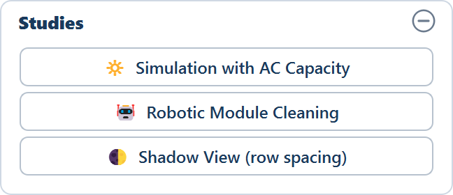
The button is the first of three in the Studies card on the Tools tab. The card is there from the start, but every button in it is greyed out until a layout exists — the simulation works from a placed layout, because it needs to know what the site can deliver before it can cap anything to a target.
It also needs two files, because typed module dimensions carry no electrical data:
Generate a layout first
Let the site fill. That first run tells you the ceiling — the most DC the usable area will take on your current settings — which is the number every target is compared against.
Load a module file
The string sizing needs the module's voltages, which come from the .PAN file
rather than from the three dimension fields. Load .PAN is on the Array
tab — see Module specifications.
Load an inverter file
The inverter's rated AC output, its current limit and its DC power limit all
come from the .OND file. Load .OND is on the Electrical tab — see
Inverters.
Without both files the button answers with a message instead of the window: "Load a PAN module file and an OND inverter file first (in the input panel), then run the AC-capacity simulation."
The window
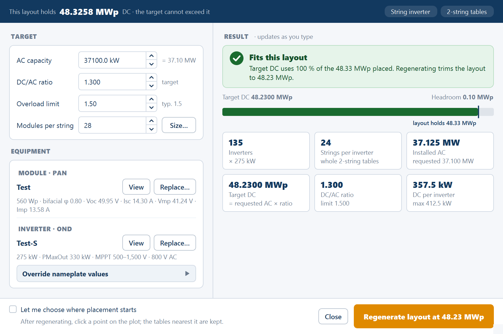
Simulation with AC Capacity is one window: inputs on the left, a live result on the right, and the action in the footer. Everything on the right updates as you type.
The strip
Across the top, the ceiling and the design: This layout holds x MWp DC · the target cannot exceed it, then chips reading String inverter or Central inverter and the table configuration as "n-string tables". The first number is the placed DC capacity of the layout you generated, and nothing in this window can raise it.
TARGET
| Field | Default | What it does |
|---|---|---|
| AC capacity | — | The AC capacity you are sizing to, in kW. The equivalent in MW is shown beside it |
| DC/AC ratio | 1.30 | Installed DC divided by installed AC — the ratio you intend to build at |
| Overload limit | 1.5 in a string design, 1.4 in a central design | The design overload limit: the highest DC/AC ratio the window will size at. This is a design figure, not the inverter's nameplate DC input |
| Modules per string | — | The string length. Size… beside it opens the string-sizing window — see String sizing |
| Strings per SMB | 20 | Central-inverter designs only. The window reports "→ n SMBs per inverter" beside it |
EQUIPMENT
Two rows, MODULE · PAN and INVERTER · OND, each with a one-line specification of the loaded file and View and Replace… buttons, so you can check or swap either file without leaving the window. Under them an expander, Override nameplate values, exposes Module Pmax in W and Inverter rated AC in kW for the case where the file's figures are not the ones you are contracting against.
RESULT · updates as you type
A verdict banner states whether the target fits, and below it Target DC and Headroom sit over a capacity meter marked "layout holds x MWp", so you can see at once how much of the placed plant the target uses. Six tiles carry the sizing:
| Tile | What it reports |
|---|---|
| Inverters | The whole number of inverters the target needs |
| Strings per inverter | Parallel strings per inverter, from the inverter's own limits |
| Installed AC | Inverter count × rated AC output — always at or above the target |
| Target DC | Requested AC × the DC/AC ratio |
| DC/AC ratio | The ratio the figures are built at |
| DC per inverter | The DC behind each inverter at that sizing |
The verdicts:
| Verdict | What it means | What the window offers |
|---|---|---|
| Fits this layout | "Target DC uses n % of the x MWp placed. Regenerating trims the layout to y MWp." — the site can deliver it | The primary button in the footer |
| Needs x MWp more than this layout holds | The first run already used all the usable area there is | "… Lower the target, or make room in the layout (tighter pitch, more area) and generate again.", with fix buttons Set AC capacity to … kW and Set ratio to … |
| DC/AC ratio is over the inverter's limit | "You asked for r; the overload limit is m. DC beyond the limit is clipped. Figures below use the limit." | Set ratio to … and Raise limit to … |
| Missing input | A field the sizing needs is empty | — |
The footer
A tick box, Let me choose where placement starts — "After regenerating, click a point on the plot; the tables nearest it are kept." — then Close and the primary button, Regenerate layout at x MWp, which names the capacity it will trim the layout to.
How it sizes
The string geometry comes first, then the inverter count, then the DC target.
Modules in series are worked out by the same string sizing method used elsewhere in the application — the module's voltage behaviour at the site's temperature extremes against the inverter's voltage window. See String sizing.
Parallel strings per inverter come from the inverter's own limits: its input current limit and its DC power limit, whichever binds first — rounded to whole tables in a string-inverter design.
The inverter count follows from the target:
num_inverters = ceil( AC_capacity / Pac_rated )

installed_ac = num_inverters × Pac_rated ≥ AC_capacity| Term | What it is |
|---|---|
AC_capacity | The AC capacity you entered |
Pac_rated | The rated AC output of one inverter, read from the inverter file — or Inverter rated AC under the override expander |
ceil( … ) | Rounded up to a whole inverter. There is no such thing as a fraction of an inverter |
num_inverters | The Inverters tile |
installed_ac | The Installed AC tile — the inverter count multiplied by the rated output |
Rounding up is the important behaviour: it never under-sizes. The installed AC capacity is always at or above your target, never below it. Where the inverter rating does not divide the target exactly you get the next whole inverter and a slightly higher installed figure — deliberately, because the alternative is a plant that cannot deliver what it was contracted for.
The target DC is then the requested AC capacity multiplied by the DC/AC ratio — the Target DC tile, and the figure in the primary button's label.
DC overload and the DC/AC ratio
The DC/AC ratio is installed DC capacity divided by installed AC capacity. A ratio of 1.4 means 1.4 MWp of modules behind every 1 MW of inverter. The window ships at 1.30.
| Inverter design | Shipped overload limit |
|---|---|
| String inverters | 1.5 |
| Central inverters | 1.4 |
Both figures are the design overload limit, and the Overload limit field lets you change them.
Why a ratio above 1 is normal
An array almost never produces its nameplate DC output. Nameplate is measured at standard test conditions, STC, and a real array is hotter than the STC cell temperature whenever irradiance is high, and below the STC irradiance level for most of the hours it generates at all. The result is that an inverter sized one to one with the array sits well below its rating for nearly all of the year.
Deliberately fitting more DC than the inverter can pass fills that gap. The array reaches the inverter's limit more often and for longer, the inverter runs nearer its efficient operating region, and on the handful of hours when the array would exceed the limit the inverter clips the surplus — it holds its output at the rating and the extra DC is not converted. The energy given up in clipping is small; the energy gained across every other hour is not. This is why utility-scale plants are routinely DC-overloaded rather than matched.
The Overload limit is the design overload figure, not the inverter's nameplate maximum DC input. Do not read 1.5 as a hardware rating you can push to. Check the manufacturer's own maximum DC input power and voltage before raising the field, and keep the warranty conditions in view — clipping is a design choice, over-driving an input is a defect. Ask for a ratio above the limit and the window says so, sizes at the limit, and offers to set the ratio down or the limit up.
The two outcomes
Once the target DC is known, it is compared against what the first layout actually placed — the figure in the strip.
The target is at or below what the layout holds
The verdict reads Fits this layout. Click Regenerate layout at x MWp and the layout is rebuilt capped to the target: the same site, the same settings, with placement trimmed so the installed DC capacity lands on your target instead of filling the ground. Tick Let me choose where placement starts first if you want to decide which end of the site keeps its tables: after the regeneration you click a point on the plot, and the tables nearest it are the ones kept.
This is the normal path. The capped layout is the one to review, export and issue, because it is the plant matching the connection you hold. The status line after the regeneration confirms it: "… | DC target x MWp met".
The target is above what the layout holds
The verdict reads Needs x MWp more than this layout holds, and no regeneration can change that — the first run already used all the usable area there is. The window offers to set the AC capacity or the ratio down to what fits.
Before accepting either, check whether the site is really the binding constraint. The usable area is the boundary shrunk by the perimeter road width, with obstructions, corridors and terrain exclusions subtracted, so a target that misses by a little may be reachable through the layout inputs rather than the commercial ones — a narrower perimeter road, half tables enabled, or Maximize placement on an awkward boundary. See Maximize placement and half tables. Change those, generate again, and reopen the window.
If a regenerated plant lands below its target, the status line says so rather than leaving you to spot it on the plot: "⚠ DC x MWp is BELOW the y MWp target — the site has no room left; reduce the AC capacity or DC/AC ratio".
Why a capped plant has empty ground
A capped layout looks wrong at first sight. There is bare ground inside the fence that tables would obviously fit on, and the instinct is that the trim overshot. It did not, and the behaviour is worth understanding before you explain the drawing to anyone else.
The delivered DC must land at or just above the target, never below. If the trim undershot, the installed DC would be less than the ratio you designed to, and the delivered DC/AC ratio would fall short of the figure the whole exercise was built around. Landing slightly high is a rounding artefact; landing low is a failure to deliver the design.
Trimmed tables are held back and returned afterwards. The stages that run after placement clear more ground: control rooms are re-placed against the reduced capacity, lightning arresters take their footprints, inverter pads take theirs. Ground that was occupied when the trim was calculated may be free by the time those stages finish. So the trimmed tables are kept in reserve and put back after them, and any whose ground has since been taken by other equipment is skipped.
Half units are weighted at half throughout. A half table counts as 0.5 wherever tables are counted in this process, so a plant using half tables is trimmed on the same weighted basis as one without them.
The consequence: the empty ground on a capped plant is deliberate. It is the capacity you chose not to build, and it is where a future extension goes if the connection is ever increased.
Where the result appears
Three rows in the ELECTRICAL group of the Summary view carry the outcome:
| Row | What it reports |
|---|---|
| AC capacity (MWac) | The plant's AC capacity |
| Inverter capacity (MW) | The installed inverter capacity |
| DC / AC ratio | The delivered DC/AC ratio |
Read all three together, and read them against the target you typed. DC / AC ratio is the check that matters: it is the delivered ratio, computed from what was actually placed, and it is the figure that tells you the cap did what you asked. A delivered ratio marginally above the target is the expected result of rounding inverters up and landing DC just above target. The DC capacity chip under the view shows the capped figure. See Summary columns for the full row set.
The capped layout carries into everything downstream unchanged — the report, the drawing exports, the bill of materials and the energy calculation all describe the capped plant, so run the energy calculation again after a regeneration.
Where it fits in the design sequence
Run an uncapped layout first
Let the site fill. That first run sets the figure in the window's strip — the most DC the usable area will take on your current settings.
Settle the layout inputs before capping
Perimeter road, obstructions, terrain, half tables, arresters: all of them move the ceiling. Capping to a target and then changing a layout input means the trim was calculated against a plant that no longer exists.
Size to the target
Enter the contracted AC capacity and the DC/AC ratio you intend to build at, and read the inverter count and target DC off the tiles.
Regenerate at the target
Click Regenerate layout at x MWp and review the plot. The bare ground is expected; check DC / AC ratio on the Summary view rather than the appearance of the plan.
Calculate energy again, then export
Energy is computed from the placed capacity, so the figures from the uncapped run no longer apply. Re-run it before exporting anything.
Where to go next
Energy charts and time-series export
The hourly energy window with its daily and monthly views, which data source is behind it, and exporting a full-year generation series at your chosen interval.
Robotic cleaning fleet
Sizing the number of cleaning robots a plant needs, and deciding gap by gap where a supported bridge will be installed.