Cables
The Cables card on the Electrical tab — whether cable runs are routed and measured, the performance notice, and the three allowances added to the DC string-cable total.
The Cables card, the second card on the Electrical tab, decides whether the application routes and measures the cables between the tables, the inverters or string monitoring boxes and the control rooms — and, when it does, what allowances are added to the DC string-cable total. Routing is off as shipped, because it is the slow step on a large plant. The equipment is placed and counted whether or not the cables are traced.
How the runs are routed once the option is on — the patterns, the trenches and the medium-voltage network — is on Cable routing. This page covers the card.
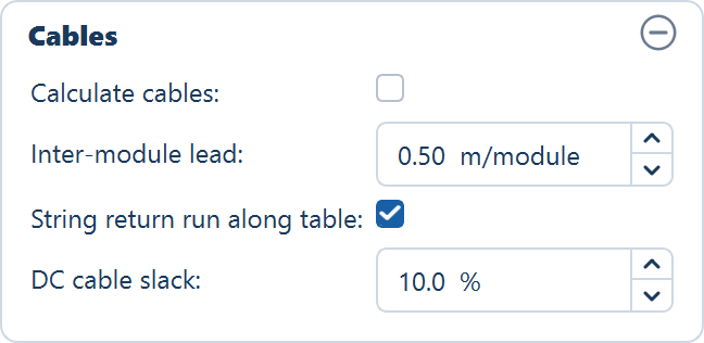
The fields
| Field | Default | Range | What it does |
|---|---|---|---|
| Calculate cables | off | — | Routes every DC and AC run on the next Generate Layout and reports the lengths |
| Inter-module lead | 0.5 m/module | 0.0–2.0 m/module | String cable allowed per module along the table, counted once per string. Fixed-tilt tables only |
| String return run along table | on | — | Adds one run back along the table per string, so both leads leave the same end. Fixed-tilt tables only |
| DC cable slack | 10.0 % | 0.0–30.0 % | Slack and wastage added to the DC string-cable total |
The Calculate cables tick is saved in a project file; the three allowances are not. A reopened project shows the defaults above for the lead, the return run and the slack, whatever you had set when you saved it.
Calculate cables
Off by default. With it off, the layout is generated, the inverters or monitoring boxes are placed and counted, and no cable is routed. With it on, the application traces every run on the next Generate Layout and reports its length.
What gets traced depends on the design, because the conversion happens in a different place:
| Run | From | To |
|---|---|---|
| String DC cable | Each table (MMS) | Its string inverter |
| AC cable | Each string inverter | Its ICR |
The inverter converts in the field, so the run into the control room is AC. The totals appear on the String DC cable (m) and AC cable to ICR (m) rows of the Summary view.
Medium-voltage runs from the control rooms to the main control room are routed in both designs, once a main control room has been placed and the layout generated again with this option on.
The performance notice
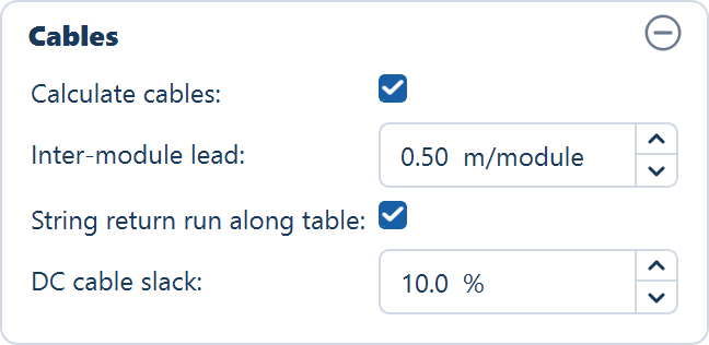
Ticking the box raises Cable Calculation — Performance Notice before anything is enabled. It reads: Cable calculation can take a long time on large or complex layouts. — It is recommended to generate the plant layout first without cable calculation, review the result, and then enable cable calculation for the final run. Do you want to enable cable calculation now?
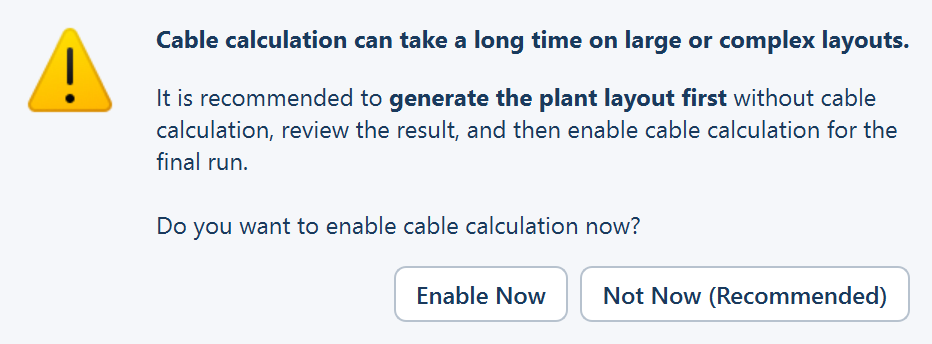
| Button | What it does |
|---|---|
| Enable Now | Leaves the box ticked. Cables are routed on the next Generate Layout |
| Not Now (Recommended) | The default. Unticks the box again |
Opening a saved project that had the option on does not raise the notice.
Take the recommendation on a plant you have not laid out before. Cable routing is the slow step on a large plant, and it is the step whose result you are least likely to keep: change the table configuration, the perimeter road, the ICR block or the strings per inverter, and every run is traced again from scratch.
What you still get with cables off
- The inverter and monitoring box counts are computed anyway. So are their ratings, the central inverter count, and everything downstream that depends on them — the AC capacity, the DC / AC ratio, the single-line diagram and the bill of materials.
- The cable rows of the Summary view show a dash. A
—on any row of the CABLES group means the value was not computed, not that it is zero. - The three cable rows of the Layers popover stay disabled, and the cable layers are left out of the CAD export.
Everything else about the design is final. Only the cable numbers are missing, and one more run with the box ticked fills them in.
The three DC allowances
The routed length of a string cable is the distance from the table to the inverter or monitoring box. Three further figures turn that into a quantity you can order against, and they are added to the DC string-cable total only.
Inter-module lead
Inter-module lead is the length of string cable allowed per module along the table — the leads that join one module to the next — and it is counted once per string. It ships at 0.5 m per module, the bill-of-quantity convention, and applies to fixed-tilt tables only.
String return run along table
A string is one row of modules across the table, so its two leads naturally end up at opposite ends of the table. String return run along table, on as shipped, adds one conductor's run back along the table per string, so that both leads exit beside each other at the same end. Untick it for U-wired strings whose leads already leave from the same end. It applies to fixed-tilt tables only.
DC cable slack
DC cable slack is the slack and wastage added to the DC string-cable total, as a percentage. It ships at 10 %, the bill-of-quantity convention.
Where to go next
Inverter settings
How many strings feed one inverter or string monitoring box, what a manufacturer inverter file changes, and where the AC figures land in the Summary view.
String sizing
The String sizing window opened from the Size… button — the three voltage limits that bound the number of modules in series, what you enter, and where the result lands.